Process and system for producing liquid biofuel from bio-based oils and/or fats

Active Publication Date: 2016-09-29
BIOALL INT GREENTECH CO LTD +1
View PDF0 Cites 1 Cited by
  • Summary
  • Abstract
  • Description
  • Claims
  • Application Information

AI Technical Summary

Benefits of technology

[0040]With a process according to the invention, fats contained in biowaste and wastewater/wastewater sludge can be utilized in an environmentally friendly and energy-efficient manner in the production of biofuel that is suitable for transportation and heating purposes. Advantageously, biofuel is biodiesel, but it can also be kerosene, for instance. Since biodiesel production with this process can be completely carried out without the use of clean water, the process saves global water resources and is particularly suitable for use in biofuel production in areas suffering from clean water scarcity (for example, densely populated Asian countries). In this process, waste fats bound to water can be utilized in biodiesel production that takes place at pressures and temperatures higher than those applied in prior art processes; in other words, it enables a broader raw material base compared to traditional technologies. The use of biogas as a catalyst can be particularly efficient if biogas is locally produced with a biogas reactor during esterification, in which case logistics costs remain minimal. In addition, glycerol can be utilized as a raw material of the biogas plant to produce biogas re

Problems solved by technology

Regarding esterification, water contained in the raw material is detrimental, because together with the base, which is used as catalyst, and fats, it forms soap instead of biodiesel.
This increases the costs of the process and reduces the total economy of the manufacture.
In prior art processes, water wash is normally used to remove acid residues from the finished bio

Method used


Image

  • Process and system for producing liquid biofuel from bio-based oils and/or fats
  • Process and system for producing liquid biofuel from bio-based oils and/or fats
  • Process and system for producing liquid biofuel from bio-based oils and/or fats

Examples


first embodiment

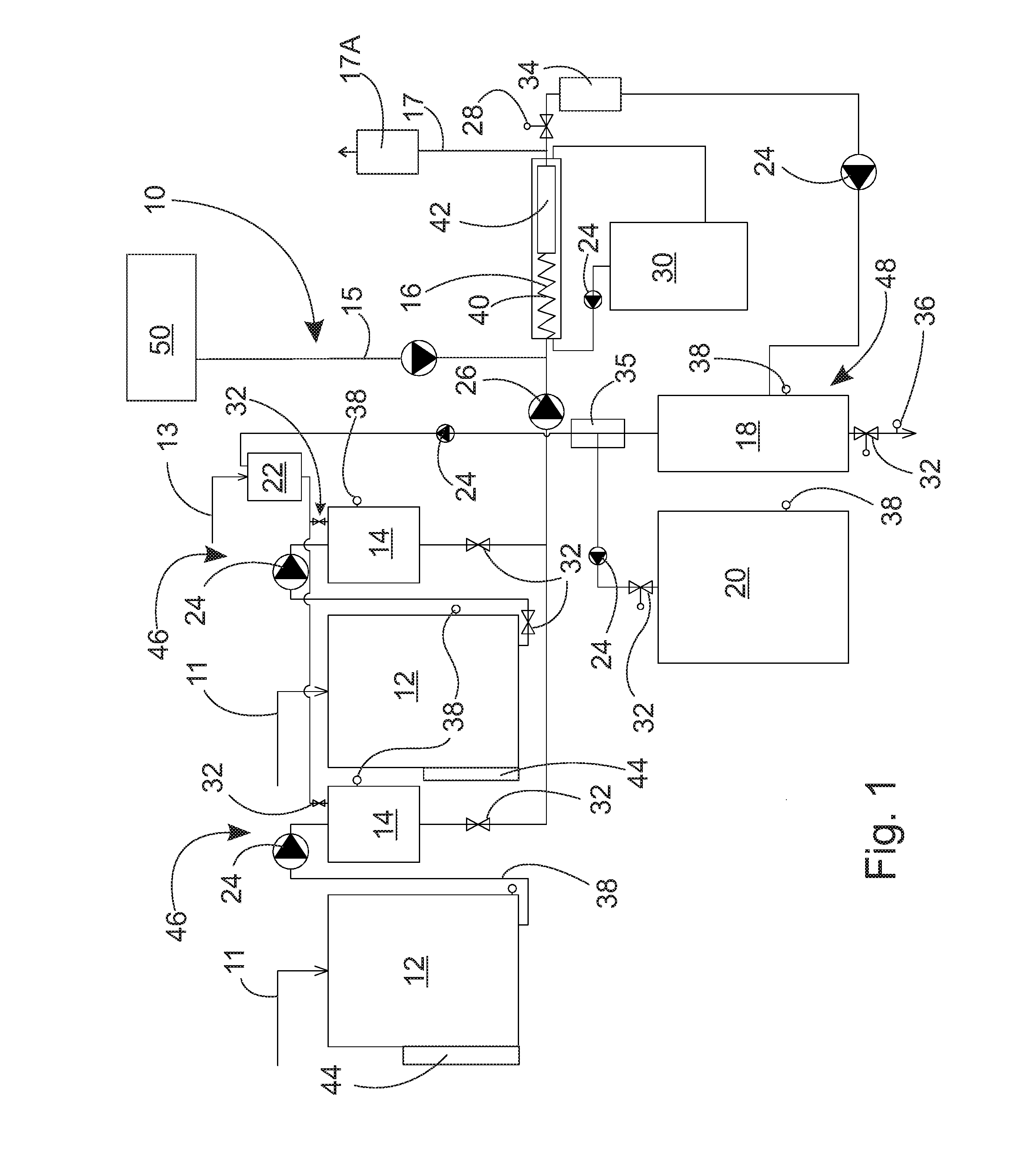
[0051]FIG. 1 illustrates the process and system according to the invention. The system according to the invention includes mixing equipment 46 for mixing alcohol 13 with a raw material 11 to form a reaction mixture, heating equipment 44 and 30 for heating the reaction mixture, and a reactor 16 for esterifying the reaction mixture to form biofuel. In addition, the system includes a pump 26 for pumping the reaction mixture to the reactor 16, adjustment equipment for adjusting the temperature and pressure of the reactor 16 in such a way that the reaction mixture is in a supercritical state, and separation equipment 48 for separating biofuel from glycerol, carbon dioxide, sulfur and alcohol. Furthermore, the system includes second separation equipment 17A for separating methane from the liquid biofuel. The above-mentioned structural components are included in all of the embodiments of the equipment meant for the realization of the process and system according to the invention.

[0052]The ...

second embodiment

[0063]FIG. 4b shows the reactor used in the system according to the invention which differs from the embodiment of FIG. 4a in terms of its heating means. In the embodiment of FIG. 4b, the heating of the reaction mixture takes place by heating the pipe 16.2 with the aid of induction coils 16.3 which form the heating means. The induction coils 16.3 are situated around the pipe 16.2 and an alternating current led into the induction coils generates an alternating magnetic field inside the induction coils, which induces circulating currents inside the induction coils 16.3 which heat the structure of the pipe 16.2. Preferably the pipe is made of black iron with an especially high resistance, so that it heats up especially efficiently due to electricity. For example, with a reactor having 60 m of pipe set on a spiral the power of the induction coils can be about 200-500 kW. In this embodiment, the reactor is also preferably insulated from the environment by a tank 16.1. In this case the ta...

third embodiment

[0064]FIG. 4c shows the reactor used in the system according to the invention which differs from the embodiment of FIG. 4a in terms of its heating means. In the embodiment of FIG. 4c, the heating of the reaction mixture takes place by heating the pipe 16.2 with the aid of electric resistors 16.4 which form the heating means. The electric resistors 16.4 can be situated at both ends of the pipe 16.2. The pipe 16.2 is preferably made of metal, which conducts electricity. An insulating stop 16.5 is formed on the pipe 16.2, the stop preventing electric current from getting conducted outside the reactor structure. For example, with a reactor having 60 m of pipe set on a spiral the power of the electric resistances can be about 200-500 kW. In this embodiment, the reactor is also preferably insulated from the environment by a tank 16.1. In this case, the tank is thermally and electrically insulated. Alternatively, the pipe itself can be used as an electric resistance.

[0065]Alternatively, th...


PUM


Abstract

A process for utilizing bio-based oils and/or fats for producing biofuels includes the steps of: mixing alcohol with a raw material for forming a reaction mixture; pumping the reaction mixture to a reactor; mixing biogas as a catalyst with the reaction mixture in a selected process step either before or after the supply of the reaction mixture to a high-pressure pump, the biogas including methane and carbon dioxide; adjusting a temperature and pressure of the reactor so that the reaction mixture achieves a supercritical state; esterifying the reaction mixture to produce liquid biofuel and by-products; separating the by-products including methane and alcohol from the liquid biofuel; and recovering separated methane. An equivalent system for utilizing bio-based oils and/or fats for producing biofuels is also disclosed.

Description

CROSS-REFERENCE TO RELATED APPLICATIONS[0001]This application is a continuation-in-part of International Patent Application No. PCT / FI2014 / 050981 filed Dec. 10, 2014, which claims the benefit of Finnish Patent Application No. 20136242 filed Dec. 11, 2013, both of which are incorporated by reference in their entirety.FIELD OF THE INVENTION[0002]The invention relate to a process and system for utilizing bio-based oils and / or fats for producing biofuels using a high pressure reactor. The invention also relates to biofuel production, particularly biodiesel production. Biodiesel is a renewable fuel corresponding to diesel oil, produced from bio-based fats and oils. Biodiesel production is based on a chemical esterification process, wherein biodiesel is produced by esterification from bio-based fats and oils in the presence of alcohol as well as an acid or a base, for example.BACKGROUND OF THE INVENTION[0003]A biodiesel manufacturing process by esterification using bio-based raw materials...

Claims


Application Information

Patent Timeline
IPC IPC(8): C11C3/00C10L1/02
CPCC11C3/003C10L1/026C10L2200/0476C10L2290/543C10L2290/24C10L2290/46C10L2290/06C10L2270/026C11B13/00Y02W30/74C07C67/00C10G3/42C10L1/19C07C67/02Y02P30/20Y02E50/10
Inventor RAUTIAINEN, MIKALEHTOMAKI, ANNIMARI
Owner BIOALL INT GREENTECH CO LTD
Why Eureka
Try Eureka