Supercharge Your Innovation With Domain-Expert AI Agents!

Sensor with moving sensitive element having mixed vibrating and pendular operation, and methods for controlling such a sensor

Active Publication Date: 2016-09-29
SAFRAN ELECTRONICS & DEFENSE
View PDF0 Cites 5 Cited by
  • Summary
  • Abstract
  • Description
  • Claims
  • Application Information

AI Technical Summary

Benefits of technology

This patent aims to improve the performance of sensors by using a single body that moves and causes a variation in the frequencies of vibration of resonators. This results in a single input and relatively large test mass for each resonator, making it easier to have surface electrostatic coupling means. The sensor can measure the movement of the first body and provide a measurement redundant to redundancy. The sensor can also be calibrated and tested. The "technical effect" of this patent is to improve the performance of sensors by using a more efficient and accurate method of measuring movement.

Problems solved by technology

Under the effect of an acceleration applied to the support, the seismic body exerts an axial force on the beam in compression or in traction: this leads to a change in the stiffness of the beam and thus to a change in its resonant frequency.
The change in the stiffness leads to a change in the frequencies of vibration of the beams.

Method used


Image

  • Sensor with moving sensitive element having mixed vibrating and pendular operation, and methods for controlling such a sensor
  • Sensor with moving sensitive element having mixed vibrating and pendular operation, and methods for controlling such a sensor

Examples


Embodiment Construction

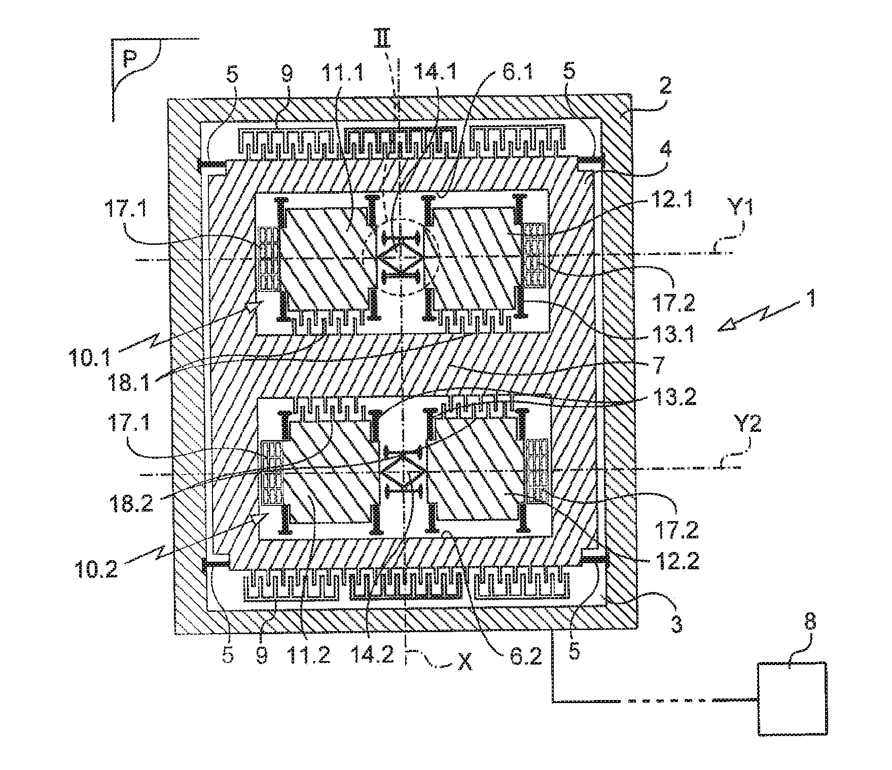
[0022]The invention is described herein in its application to measuring acceleration. Naturally, the invention is nevertheless not limited to this application.

[0023]The sensor of the invention in this example is of the MEMS type and it is fabricated by etching wafers that comprise at least a semiconductor layer and an electrically conductive layer separated by an electrically insulating layer, known as silicon on insulator (SOI) wafers. This method of fabrication is itself known.

[0024]The sensor of the invention comprises a stand given overall reference 1. The stand 1 has a side wall 2 in the form of a rectangular frame arranged on a bottom 3.

[0025]A first body 4, which in this example is a so-called seismic “body”, is mounted on the stand via first suspension means 5 connecting the body 4 to the side wall of the stand 1. The suspension means 5 define a suspension plane P and they are arranged so that the body is movable along a sensing axis X contained in the suspension plane P.

[00...


PUM


Abstract

A sensor comprising: a stand; a first body movable along a sensing axis; two pairs of second bodies arranged symmetrically relative to the first body and along the sensing axis; transducers for detecting a position of the first body relative to the stand, for setting the second bodies into vibration along a vibration axis, and for detecting respective vibration frequencies of the second bodies; and surface electrostatic coupling means connecting each second body to the first body in such a manner that a movement of the first body relative to the stand along the sensing axis gives rise respectively to an increase and to a decrease in the electrostatic coupling for one and the other of the pairs of second bodies. Methods of controlling such a sensor.

Description

BACKGROUND OF THE INVENTION[0001]1. Field of the Invention[0002]The present invention relates to a sensor usable for detecting an acceleration, a pressure, or more generally any physical magnitude for which a variation can cause a movable body to move relative to a stand. The invention is more particularly suitable for use in an application to an inertial acceleration sensor, and in particular a sensor of microelectromechanical system (MEMS) type.[0003]2. Brief Discussion of the Related Art[0004]An acceleration sensor having a vibrating resonator generally comprises a seismic body (or test mass) connected to a support by a vibrating element that is generally in the form of a beam extending along a sensing axis of the sensor. The sensor has transducers for setting the beam into vibration at the resonant frequency of the beam and for detecting variations in the frequency of vibration of the beam. Under the effect of an acceleration applied to the support, the seismic body exerts an ax...

Claims


Application Information

Patent Timeline
IPC IPC(8): G01P15/097
CPCG01P15/097G01P2015/0814G01P2015/082G01P2015/0848G01C19/5656G01C19/5719G01P15/125G01P15/18G01P15/14G01C19/5733G01P15/0888G01C19/5642G01C19/56G01P15/0802G01P2015/0857G01P15/0975
Inventor JEANROY, ALAIN
Owner SAFRAN ELECTRONICS & DEFENSE
Features
  • R&D
  • Intellectual Property
  • Life Sciences
  • Materials
  • Tech Scout
  • Unparalleled Data Quality
  • Higher Quality Content
  • 60% Fewer Hallucinations
Learn More