System for non-destructive inspection of structural components

Active Publication Date: 2016-10-13
AIRBUS OPERATIONS GMBH
View PDF8 Cites 4 Cited by
  • Summary
  • Abstract
  • Description
  • Claims
  • Application Information

AI Technical Summary

Benefits of technology

[0020]In a further preferred embodiment, at least one bar comprises at least two threaded holes extending in parallel, the distance of the holes being identical for each bar, and at least two threaded rods are provided, which extend through the threaded holes and in the plane defined by the contact face. With such an adjusting device it is possible to adapt the distance between the bars by simply rotating the threaded rods. In this way, the distance between the bars can be set in a simple way in order to match the distance between the bars to a specific wavelength.
[0021]In another preferred embodiment, the ultrasonic probe comprises a sonotrode on which the contact face is provided, and a housing which receives the sonotrode and comprises an opening

Problems solved by technology

This friction results in a generation of heat at the location of the defect, i.e., a conversion of ultrasonic energy into thermal energy takes place at the position of the defect.
However, the prior art is characterized by a high initial energy i

Method used


Image

  • System for non-destructive inspection of structural components
  • System for non-destructive inspection of structural components
  • System for non-destructive inspection of structural components

Examples


first embodiment

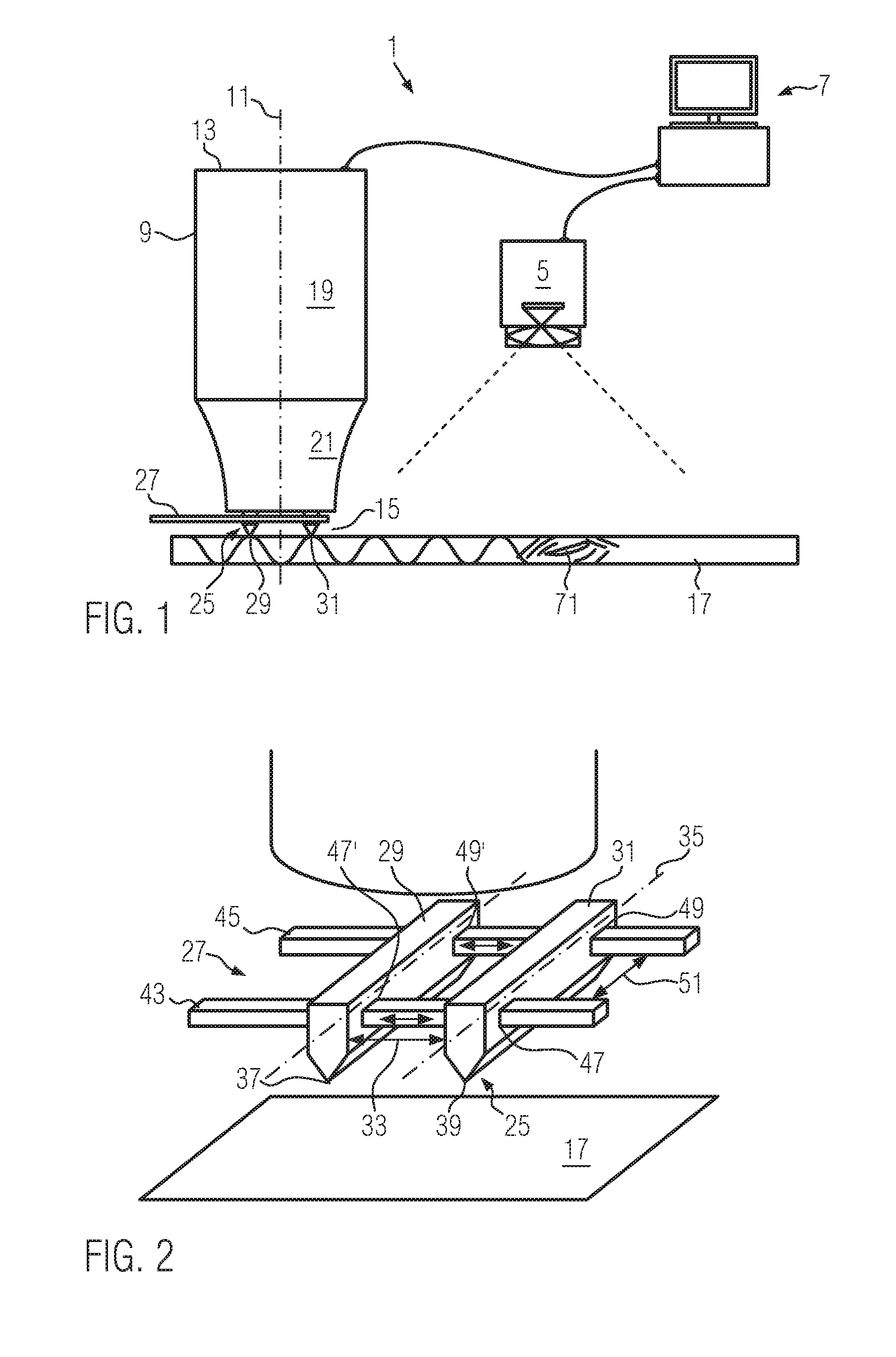
[0033]FIG. 1 shows a system 1 for non-destructive inspection of a structural component according to the present invention. The system 1 for non-destructive inspection comprises an ultrasonic probe 3, a thermal imaging camera 5 and a control unit 7.

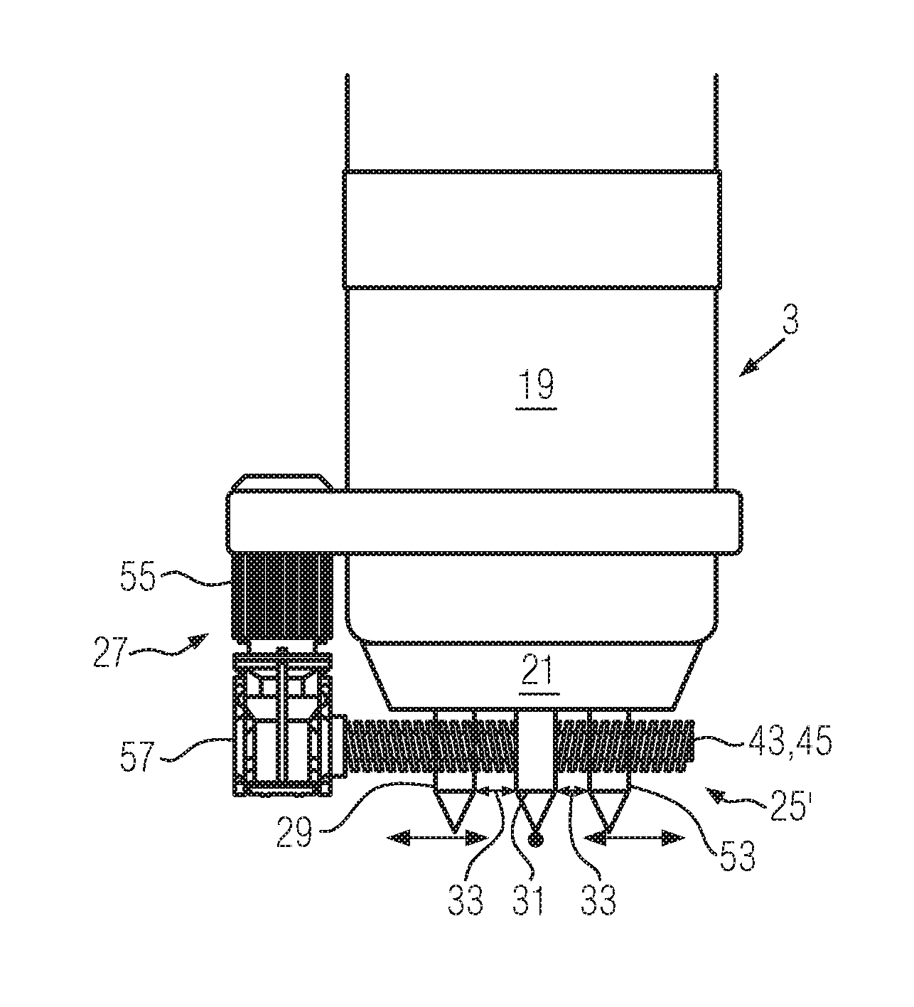
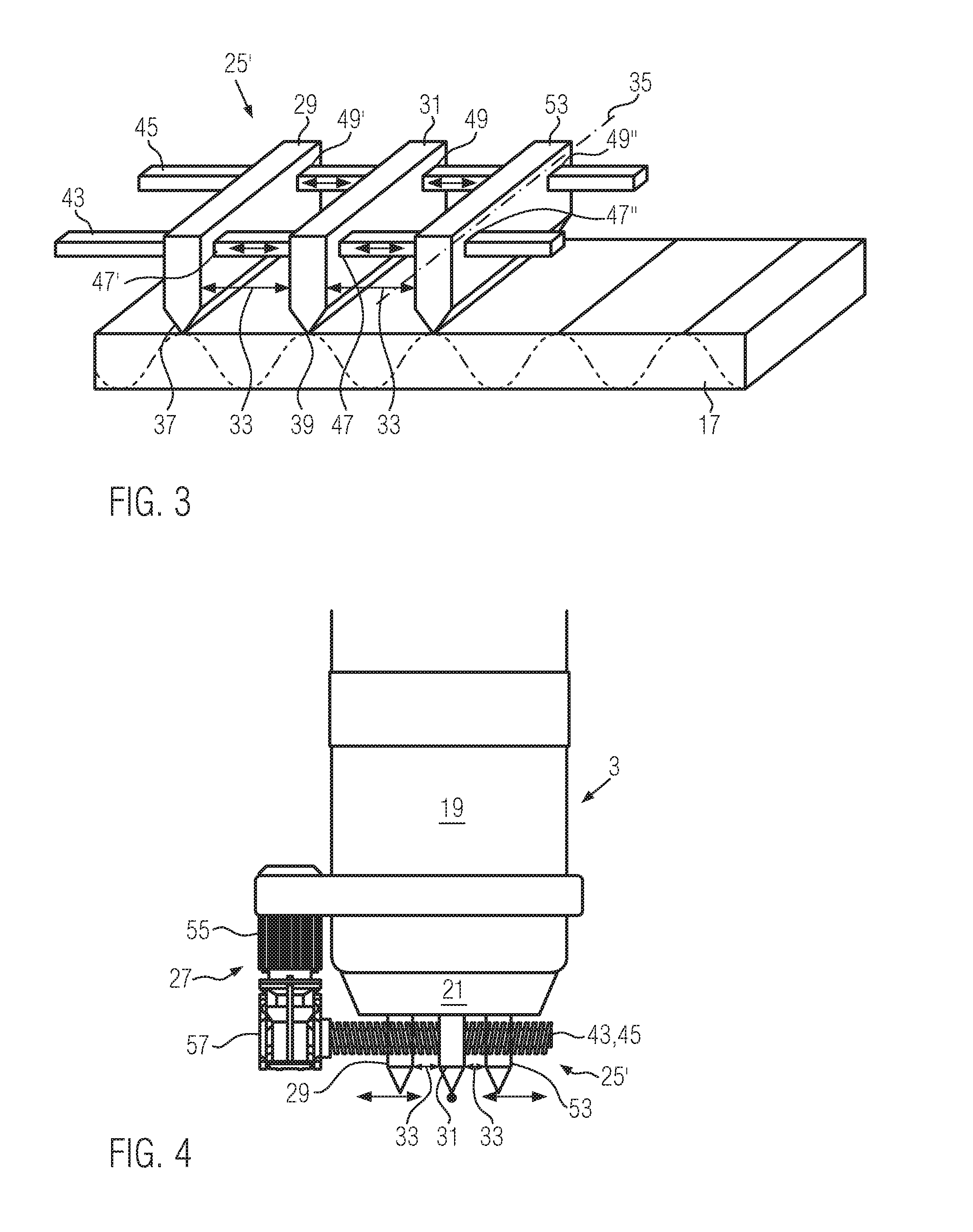
[0034]The ultrasonic probe 3 has a substantially cylindrical casing 9 that extends along a longitudinal axis 11 having a first end surface 13 and a contact face 15, which is opposite the first end surface 13 in the direction of the longitudinal axis 11 of the ultrasonic probe 3. The surface 13 and the face 15 of the ultrasonic probe 3 are perpendicular to the longitudinal axis 11, wherein the contact face 15 is intended to contact a surface of a structural component 17 that has to be inspected. The structural component 17 is formed of a special carbon fiber reinforced plastic (CFRP) or any other material, e.g., material which can be employed to form the outer skin of an aircraft.

[0035]The ultrasonic probe 3 is adapted to emit ultrasonic en...

second embodiment

[0047]FIG. 9 shows a system 1 for non-destructive inspection of structural components 17. In this embodiment, the ultrasonic probe 3 comprises a housing 73 in which the piezoelectric element 19 and the sonotrode 21 together with the bar assembly 25′ and the adjusting device 27 are received. The bar assembly 25′ is identical to the assembly shown in FIG. 3 and comprises three wedge-shaped bars 29, 31, 53. The housing 73 has a cylindrical cross section with a closed top end 75 and a bottom opening 77 opposite the top end 75 with respect to the longitudinal axis 11. The bottom opening 77 is surrounded by an annular closed rim 79 formed of elastic rubber material, the rim 79 extending in the plane 81 of the contact face 15 and being adapted to abut on a surface of a component 17 to be inspected. When this is the case, the housing 73 and the component 17 delimit a closed volume in which the sonotrode 21 is received.

[0048]The top end 75 of the housing 73 supports the piezoelectric element...


PUM


Abstract

A system for non-destructive inspection of structural components comprising an ultrasonic probe having a contact face for contacting a surface of a structural component to be inspected and being adapted to emit ultrasonic energy into the structural component when the contact face abuts on a surface of the structural component, a thermal imaging camera adapted to inspect a portion of a surface of the structural component to detect region of the surface of the structural component where an increase of the temperature occurs, and a control unit connected to the ultrasonic probe and the thermal imaging camera. The contact face extends in a plane and is provided with at least two bars which are arranged in parallel and have a common separation distance from each other.

Description

CROSS-REFERENCES TO RELATED APPLICATIONS[0001]This application claims the benefit of the European patent application No. 15162660.3 filed on Apr. 7, 2015, the entire disclosures of which are incorporated herein by way of reference.BACKGROUND OF THE INVENTION[0002]The present invention relates to a system for non-destructive inspection of structural components.[0003]Non-destructive inspection of the sub-surface region of structural components is particularly important in the industrial sector, e.g., in the aviation industry where especially aircraft outer skin components need to be inspected to monitor their structural integrity. For example, after an accidental damage of an aircraft due to an outside impact, such as a stroke of lightning or a bird strike, it is important to examine the state of the sub-surface region in the respective skin element of the fuselage or wing.[0004]Thus, inspection methods have been developed to inspect sub-surface defects in structural components withou...

Claims


Application Information

Patent Timeline
IPC IPC(8): G01N29/24G01J5/02
CPCG01N29/2437G01J5/02G01N2291/0235G01N2291/028G01J2005/0077B06B3/00G01N25/72G01N29/221G01N29/2487G01N2291/0231G01N2291/0258G01N2291/0425G01N2291/0427G01N2291/2694G10K11/002
Inventor BISLE, WOLFGANGSCHERLING, DIETERBOCK, FREDERICRAHAMMER, MARKUSSOLODOV, IGOR
Owner AIRBUS OPERATIONS GMBH
Why Eureka
Try Eureka