Logic circuit generation device and method

a logic circuit and generation device technology, applied in the field of synthesizing a semiconductor integrated circuit, can solve the problems of easy degradation of design quality, failure to complete verification, etc., and achieve the effects of high efficiency, high description flexibility, and high quality

Active Publication Date: 2016-10-13
TOKYO INST OF TECH
View PDF7 Cites 28 Cited by
  • Summary
  • Abstract
  • Description
  • Claims
  • Application Information

AI Technical Summary

Benefits of technology

[0035]The device and the method of the present invention can automatically generate an RTL description that can be logic synthesized from a software description with high description flexibility, and thus can design, develop, and verify a large-scale integrated circuit with high quality and high efficiency in a short period, with low cost.

Problems solved by technology

Accordingly, in the case of designing a logic circuit that needs a complicated data flow control, for example, a high-performance LSI for image processing applications, there are problems, such as a failure of full verification to verify the flow of the state transition, and the easy degradation in the design quality due to inclusion of a bug or the like.

Method used


Image

  • Logic circuit generation device and method
  • Logic circuit generation device and method
  • Logic circuit generation device and method

Examples


Embodiment Construction

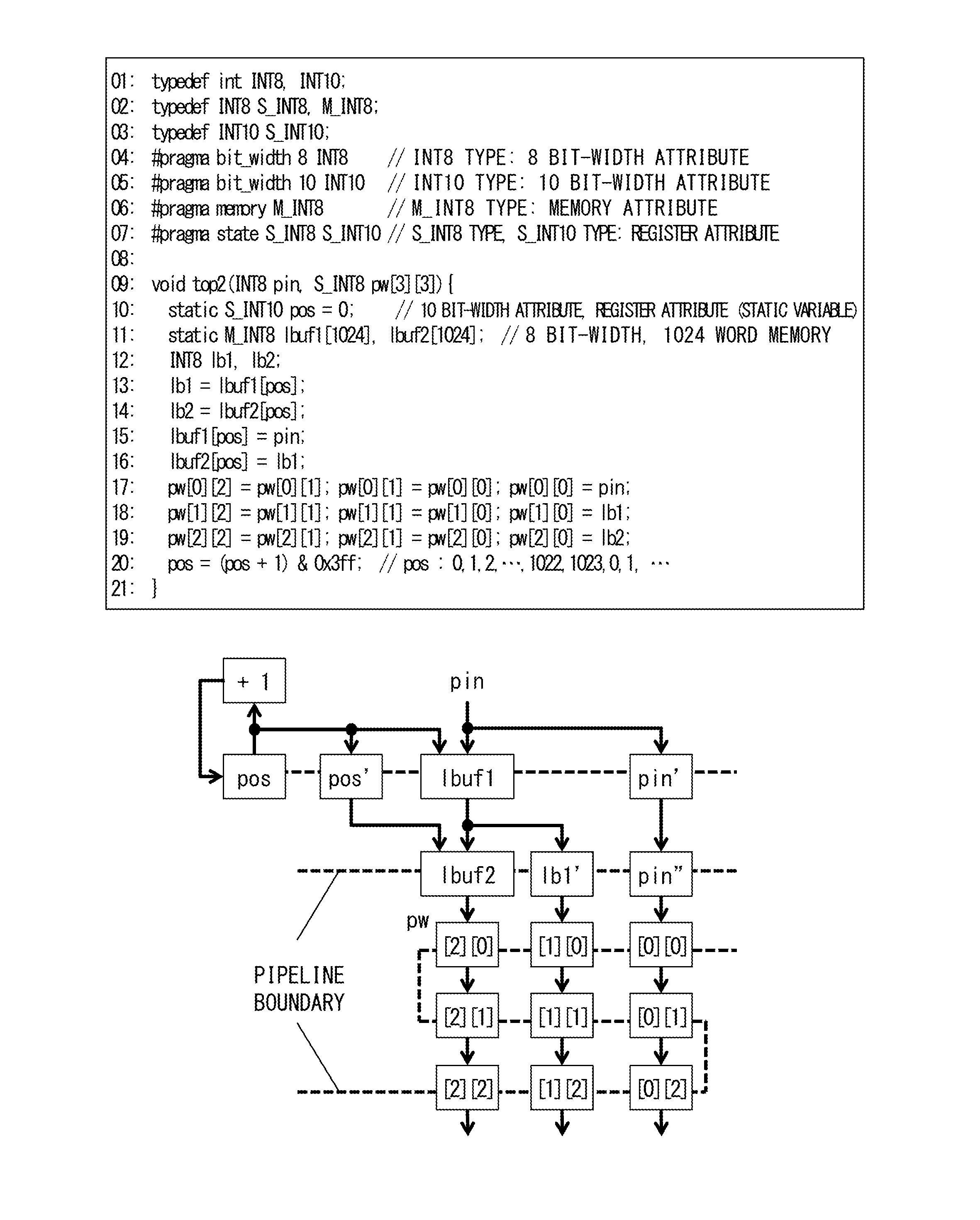
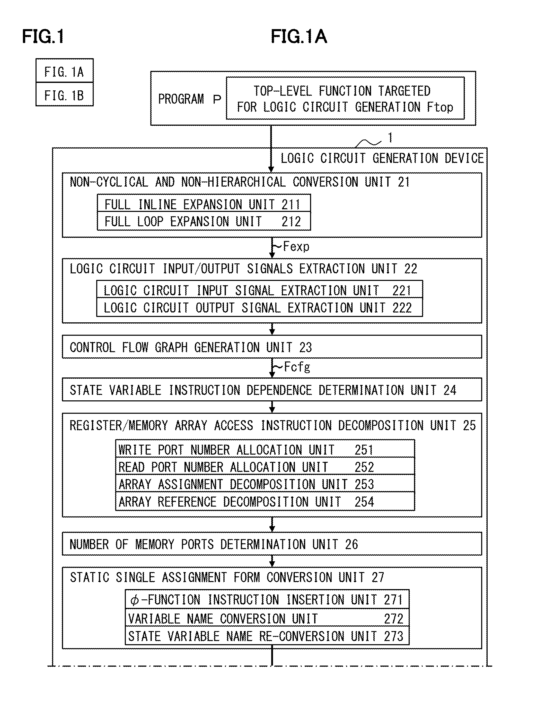
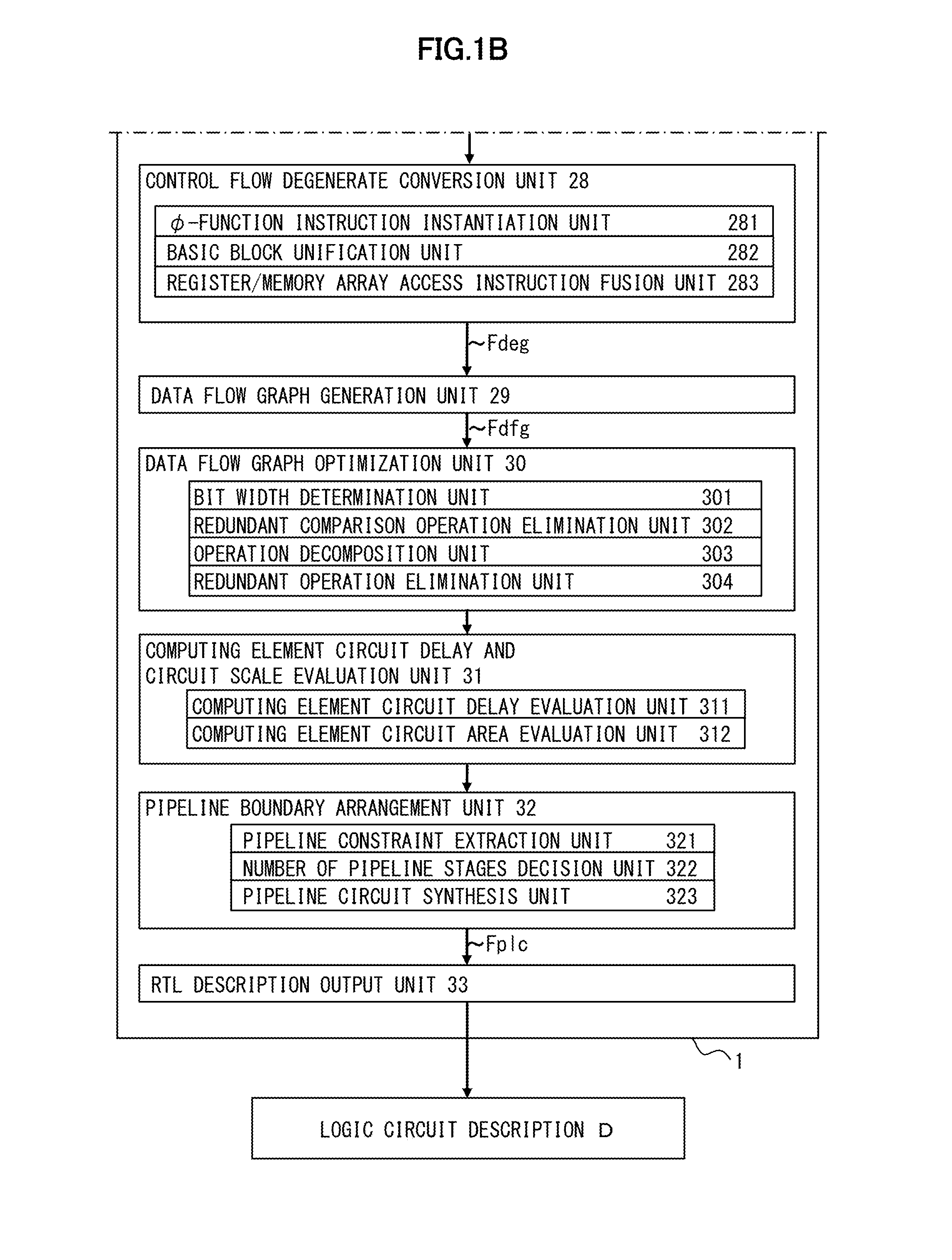
[0080]Hereinafter, an embodiment of the present invention will be explained with reference to the accompanying drawings (FIG. 1 to FIG. 37) below. FIG. 1 illustrates an example block diagram illustrating a function of a logic circuit generation device according to the embodiment of the present invention. As illustrated in FIG. 1, a logic circuit generation device 1 can use a program P including a top-level function Ftop targeted for a logic circuit generation as an input, and output a logic circuit description D representing a logic circuit. The logic circuit generation device 1 can include:

[0081]a non-cyclical and non-hierarchical conversion unit 21;

[0082]a logic circuit input / output signals extraction unit 22;

[0083]a control flow graph generation unit 23;

[0084]a state variable instruction dependence determination unit 24;

[0085]a register / memory array access instruction decomposition unit 25;

[0086]a number of memory ports determination unit 26;

[0087]a static single assignment form ...


PUM


Abstract

A specific information processing function, which assumes circuit implementation, is described in a programming language, and from this description, an RTL description that can be logic synthesized is automatically generated. A logic circuit generation device includes: a control flow graph generation unit that generates a control flow graph; a control flow degenerate conversion unit that generates a control flow degenerate program by removing all condition branch instructions from the control flow graph; a data flow graph generation unit that generates a data flow graph from the control flow degenerate program; and a logic circuit description output unit that generates logic circuit description indicating a sequential circuit in which a rooted branch of the data flow graph corresponds to the wiring of the logic circuit and a node of the data flow graph corresponds to a computing element of the logic circuit.

Description

TECHNICAL FIELD[0001]The present invention relates to a method of synthesizing a semiconductor integrated circuit, and more specifically, relates to a method of synthesizing a logic circuit from a logic circuit description that is described using a programming language.BACKGROUND ART[0002]Conventionally, logic circuit designs of large-scale integrated (LSI) circuits have been made by using the designs of a register transfer level (RTL) description, and by performing data flow controls using state transition diagrams. The RTL expresses the level of abstraction of the logic circuit design, and the RTL description is a kind of a description method by a hardware description language (HDL) with the low level of abstraction that describes the structure and the operation of hardware. In the RTL, a flow of data is described at the register level. A source code of the HDL that is described in the RTL is converted into a logic-gate level circuit description using software, which is called a l...

Claims


Application Information

Patent Timeline
Patent Type & Authority Applications(United States)
IPC IPC(8): G06F17/50
CPCG06F17/505G06F30/327G06F30/30G06F30/33
Inventor ISSHIKI, TSUYOSHI
Owner TOKYO INST OF TECH
Why Eureka
Try Eureka