Biocompatible and Implantable Optical Conduits

a technology of optical conduits and biocompatible materials, applied in the field of optical conduit assemblies, can solve the problems of microelectrode implants that fail in long term, device failure for chronic implantation, and mechanical stress at the device-tissue interface, and achieve the effect of sufficient efficiency

Active Publication Date: 2016-10-20
NEW JERSEY INSTITUTE OF TECHNOLOGY
View PDF2 Cites 1 Cited by
  • Summary
  • Abstract
  • Description
  • Claims
  • Application Information

AI Technical Summary

Benefits of technology

[0010]For example, in those applications where the targeted implant sites are away from a bony structure like the skull or vertebrae, optical energy harvested subcutaneously needs to be transferred to the location of the implant with sufficient efficiency. This optical harvesting and transfer system should be robust enough to

Problems solved by technology

However, microelectrode implants often fail in long term because of tethering forces of the connecting wires.
Also, there is a mechanic stress that occurs at the device-tissue interface because the microelectrode is a rigid body flo

Method used


Image

  • Biocompatible and Implantable Optical Conduits
  • Biocompatible and Implantable Optical Conduits
  • Biocompatible and Implantable Optical Conduits

Examples


example 1

[0065]Multi-electrode arrays (“MEAs”) have employed technologies to produce fine 2D and 3D constructs by attempting to optimize the electrode mechanical properties between flexibility and robustness. These MEAs are being used as a research tool in animal models and in some clinical trials. In general, MEAs are well suited for cortical implants where the targeted neural structures are beneath the skull and where they experience relatively small movements. Typically, those arrays cease to function after a few years due to neural tissue scarring that forms around the electrode shanks, and they have to be explanted at the end of the study from the subject. The tethering of the inter-connecting wires or ribbon cables is believed to be the major cause of the on-going tissue response in long-term implants. The rigidity of the shanks and the substrate exacerbate the mechanical stress induced by the tethers.

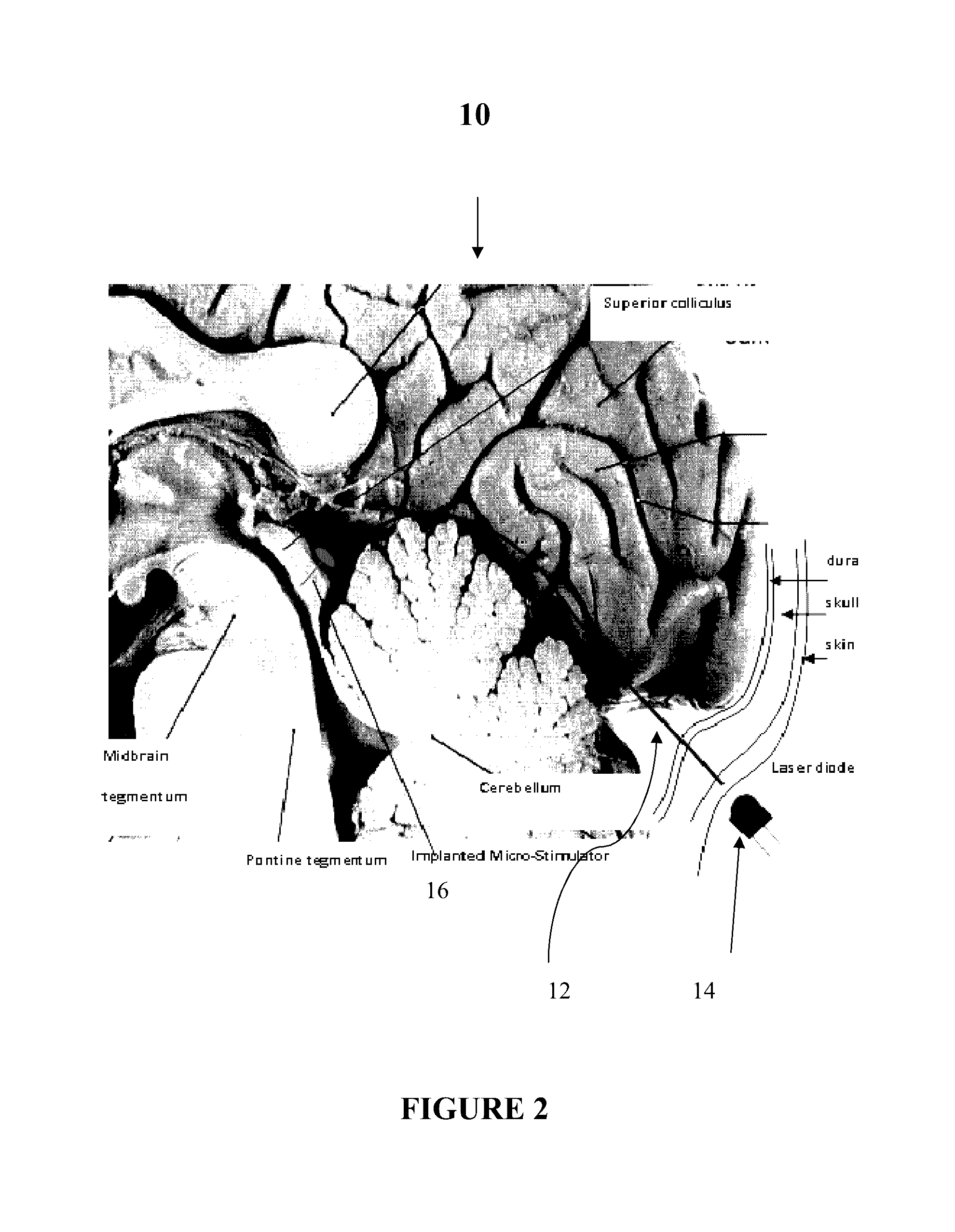
[0066]Some micro-stimulation ideas in the CNS cannot be tested with chronic implants ...

example 2

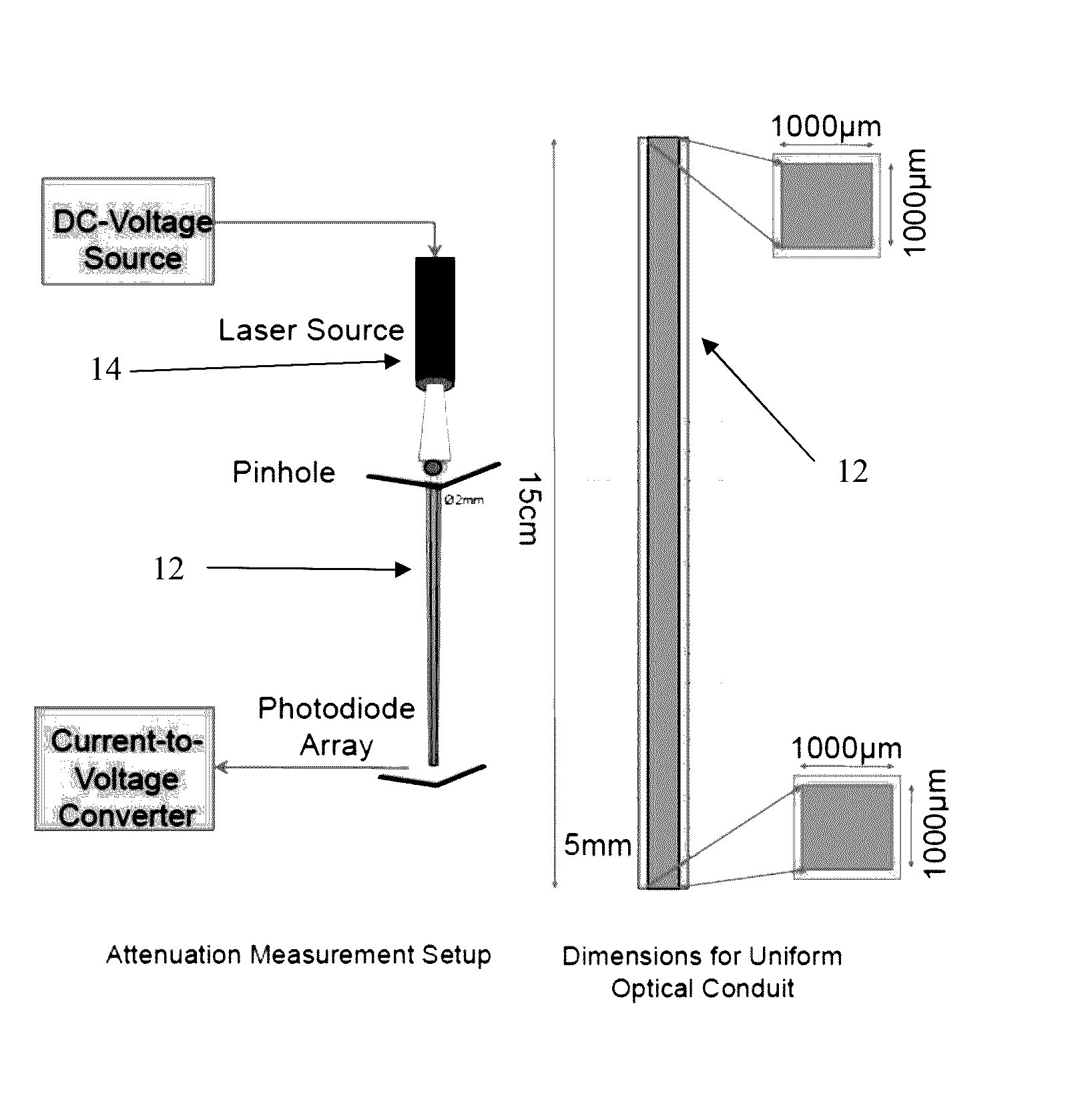
A PDMS-Based Optical Waveguide for Transcutaneous Powering of Microelectrode Arrays

[0078]Implantable microelectrode arrays (“MEAs”) usually have on-site electronics that need to be powered, both in neural recording and stimulation applications. Interconnecting wires between implanted electrodes and the outside world constitute a major source of complications. One exemplary solution to this tethering problem is to provide a light waveguide that can collect the optical power transcutaneously and transmit it to the microelectrode array, where it is converted to an electric current. A PDMS-based waveguide was fabricated and its attenuation was found to be 0.36 dB / cm in vitro. The skin flap of the thenar web space in the hand was used to test the photon collection efficiency of the waveguide in diffused light. The efficiency of the waveguide alone was 44 plus / minus 11% (mean plus / minus std) as measured in 13 subjects with different skin pigmentations, excluding the attenuation within the...


PUM


Abstract

The present disclosure provides advantageous optical conduit assemblies (e.g., biocompatible and implantable optical conduit assemblies), and related methods of use. More particularly, the present disclosure provides advantageous optical conduit assemblies (e.g., polydimethylsiloxane (“PDMS”)-based optical conduit assemblies) configured to power implantable devices (e.g., neural micro-stimulators or deep brain stimulators or the like) or to be used in optogenetic stimulation. In general, the exemplary optical conduit assemblies can be used for applications where energy needs to be transmitted to deep locations inside the body or brain without using electrical wires. Therefore, implantable devices that need to be powered (e.g., neural prosthetics) can be powered from an external light source using an optical conduit and an optical-to-electrical converter (e.g., a photodiode) attached to the end of the optical conduit on the inside.

Description

CROSS-REFERENCE TO RELATED APPLICATIONS[0001]This application claims the benefit of U.S. Provisional Application entitled “System And Method For Light Conduits Made From Biocompatible Materials For Implantation,” which was filed on Apr. 15, 2015, and assigned Ser. No. 62 / 148,152, the contents of which are herein incorporated by reference in their entirety.STATEMENT REGARDING FEDERALLY SPONSORED RESEARCH[0002]This invention was made with government support from the National Institutes of Health under grant and / or contract NIBIB RO1 EB009100 and NINDS RO1 NS0785. The government has certain rights in this invention.FIELD OF THE DISCLOSURE[0003]The present disclosure relates to optical conduit assemblies (e.g., implantable optical conduit assemblies) and related methods of use and, more particularly, to optical conduit assemblies (e.g., polydimethylsiloxane (“PDMS”)-based optical conduit assemblies) configured to power implantable devices (e.g., neural micro-stimulators such as deep bra...

Claims


Application Information

Patent Timeline
IPC IPC(8): A61N1/378A61N5/06A61N1/36
CPCA61N1/3787A61N1/3605A61N2005/067A61N2005/063A61N2005/0651A61N5/0622A61N2005/0612A61N1/37217H02J50/30A61N5/067H02J2310/23
Inventor SAHIN, MESUTERSEN, ALI
Owner NEW JERSEY INSTITUTE OF TECHNOLOGY
Why Eureka
Try Eureka