
High-voltage supply unit and circuit arrangement for generating a high voltage for a particle beam apparatus

a technology of high-voltage supply and particle beam, which is applied in the direction of electrical equipment, electric discharge tubes, basic electric elements, etc., can solve the problems of only providing high-voltage supply units, high-voltage supply units used in particle beam apparatuses, and 1-quadrant operation

Active Publication Date: 2016-10-27
CARL ZEISS MICROSCOPY GMBH
View PDF3 Cites 7 Cited by
  • Summary
  • Abstract
  • Description
  • Claims
  • Application Information

AI Technical Summary

Benefits of technology

The patent describes a high-voltage supply unit that reduces power losses and noise in the output voltage. The unit has two current sources that can be adjusted or controlled to achieve the desired output current. The adjustment or control loop acts on both current sources, resulting in a reduction in power losses and noise in the output voltage. The unit also has a feedback unit with a capacitive voltage divider to measure the output voltage more quickly and adjust the second current more quickly. The feedback unit helps to reduce residual ripple and noise in the output voltage. The circuit arrangement also includes a holder and cooling unit for the resistors, which ensures that the resistors have a similar thermal resistance to the cooling unit. This prevents changes in the resistor divider ratio due to temperature differences and ensures a stable and accurate output voltage.

Problems solved by technology

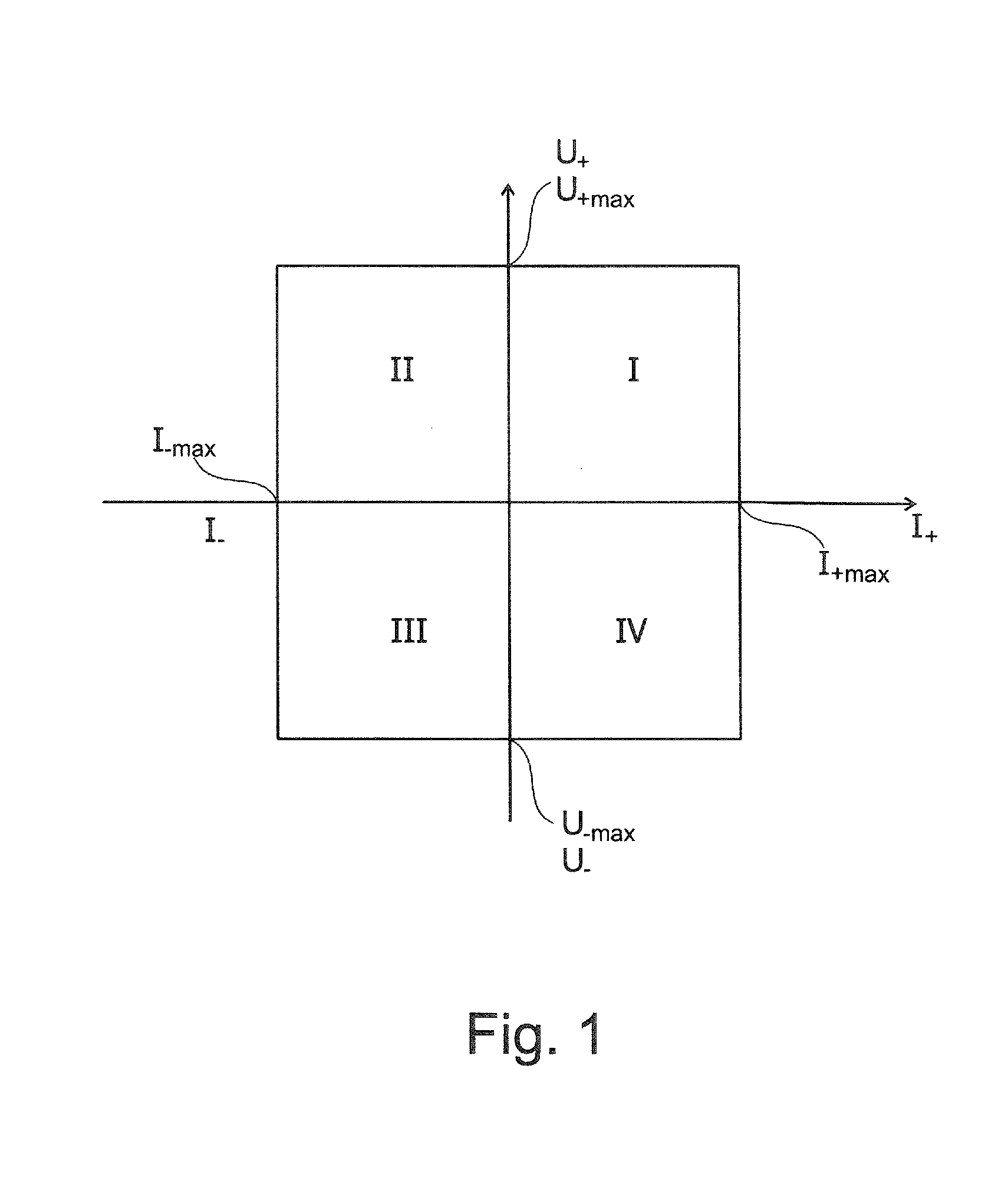
The high-voltage supply units used in the particle beam apparatuses are disadvantageous in that they only enable a 1-quadrant operation.
This means that the known high-voltage supply units can only provide voltage values which are assignable to a single quadrant.

Method used


Image

  • High-voltage supply unit and circuit arrangement for generating a high voltage for a particle beam apparatus
  • High-voltage supply unit and circuit arrangement for generating a high voltage for a particle beam apparatus
  • High-voltage supply unit and circuit arrangement for generating a high voltage for a particle beam apparatus

Examples


Embodiment Construction

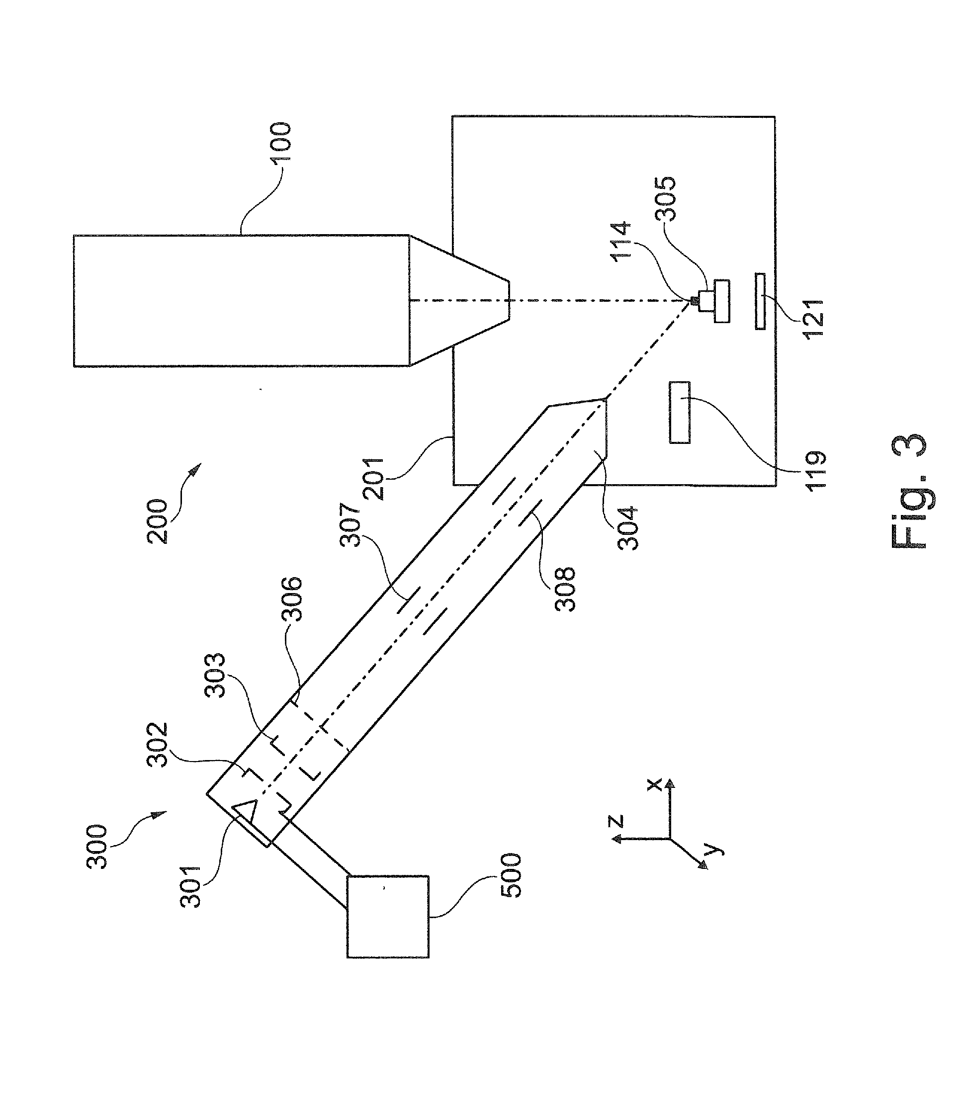
[0051]The system described herein is now explained in more detail by means of particle beam apparatuses in the form of an SEM and in the form of a combination apparatus, which has an electron beam column and an ion beam column. Reference is explicitly made to the fact that the system described herein can be used in any particle beam apparatus, in particular in any electron beam apparatus and / or in any ion beam apparatus.

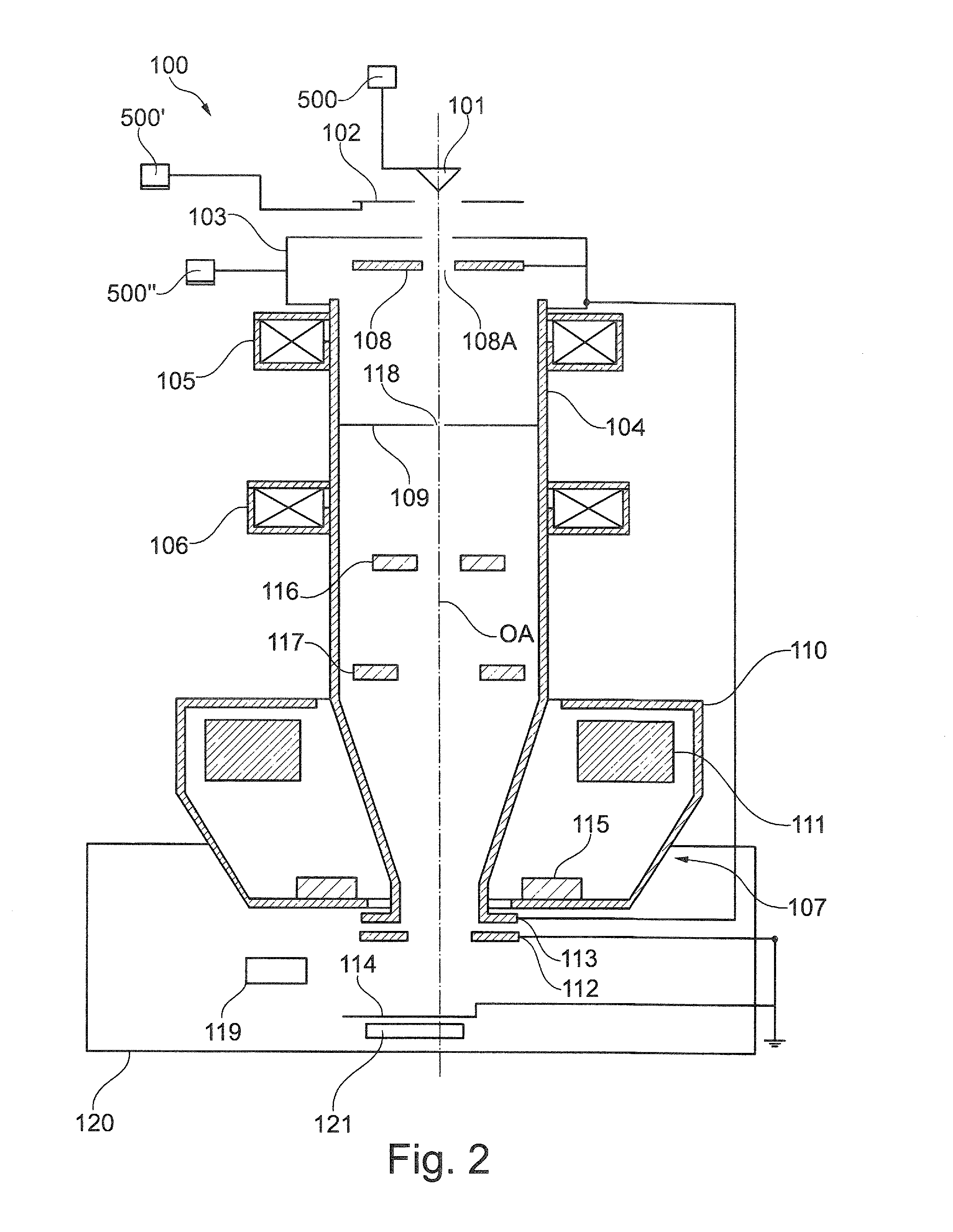
[0052]FIG. 2 shows a schematic illustration of an SEM 100. The SEM 100 has a first beam generator in the form of an electron source 101, which is embodied as a cathode. Furthermore, the SEM 100 is provided with an extraction electrode 102 and with an anode 103, which is placed onto one end of a beam guiding tube 104 of the SEM 100. By way of example, the electron source 101 is embodied as thermal field emitter. However, the invention is not restricted to such an electron source 101. Rather, any electron source is utilizable.

[0053]The electron source 101 is at a high ...


PUM


Abstract

The system described herein relates to a high-voltage supply unit for providing an output voltage for a particle beam apparatus, wherein the particle beam apparatus is embodied as, for example, an electron beam apparatus and / or an ion beam apparatus. The system described herein is based on the fact that it was recognized that a bipolar voltage supply unit can be formed by means of a unipolar first current source and a unipolar second current source, said bipolar voltage supply unit enabling a load current in two directions. The high-voltage supply unit according to the system described herein can be operated in the 4-quadrant operation. In the 4-quadrant operation, a first voltage source for supplying the first current source and a second voltage source for supplying the second current source are embodied as different voltage sources.

Description

TECHNICAL FIELD[0001]The system described herein relates to a high-voltage supply unit for providing an output voltage for a particle beam apparatus such as an electron beam apparatus and / or an ion beam apparatus and more particularly to a circuit arrangement for generating a high voltage for a particle beam apparatus and a resistor circuit arrangement for the aforementioned high-voltage supply unit.BACKGROUND OF THE INVENTION[0002]Electron beam apparatuses, in particular a scanning electron microscope (also referred to as SEM below) and / or a transmission electron microscope (also referred to as TEM below), are used to examine objects (also referred to as samples) in order to obtain knowledge in respect of the properties and behavior of the objects under certain conditions.[0003]In an SEM, an electron beam (also referred to as primary electron beam below) is generated by means of a beam generator and focused on an object to be examined by way of the beam guiding system. An objective...

Claims


Application Information

Patent Timeline
Patent Type & Authority Applications(United States)
IPC IPC(8): H01J37/24H01J37/28
CPCH01J37/28H01J37/241H01J2237/002
Inventor FICHTER, EDGARFOBER, JOERGPREIKSZAS, DIRKHENDRICH, CHRISTIANSCHNELL, MICHAELMOMMSEN, MOMME
Owner CARL ZEISS MICROSCOPY GMBH
Learn More