Multi-functional chamber housing a biological component

a biological component and multi-functional technology, applied in the field of extracorporeal liver perfusion, can solve the problems of limited treatment, lack of donor organs, and purely artificial systems, which cannot replace all liver functions,

a biological component and multi-functional technology, applied in the field of extracorporeal liver perfusion, can solve the problems of limited treatment, lack of donor organs, and purely artificial systems, which cannot replace all liver functions,

US20160316742A1Inactive Publication Date: 2016-11-03UNIV COLLEGE OF LONDON

Image

  • Multi-functional chamber housing a biological component
  • Multi-functional chamber housing a biological component
  • Multi-functional chamber housing a biological component

Examples


Embodiment Construction

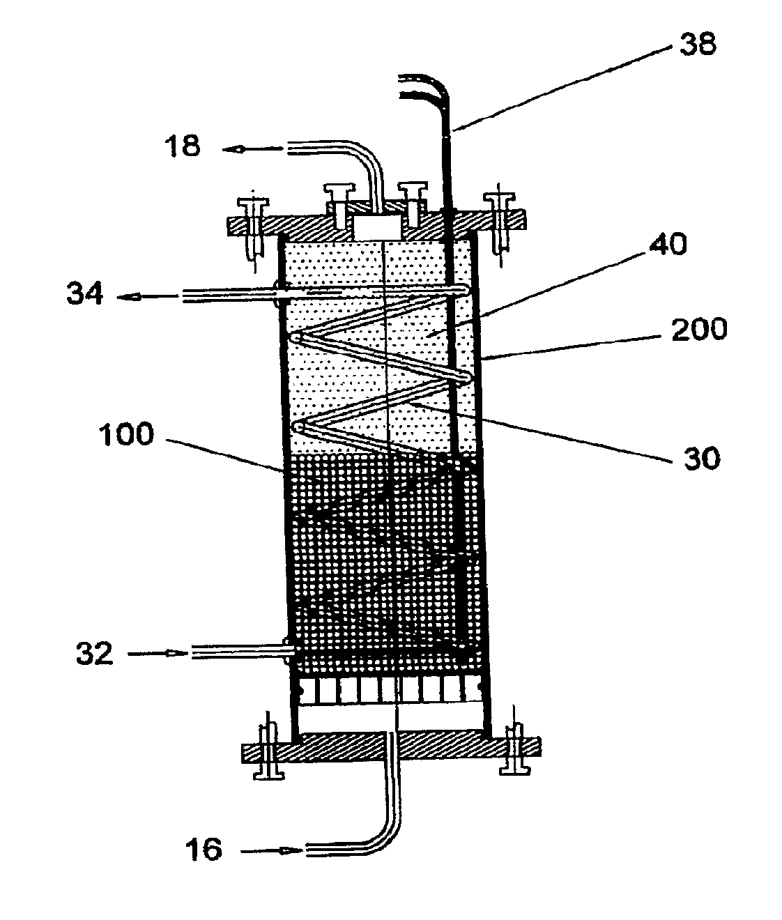
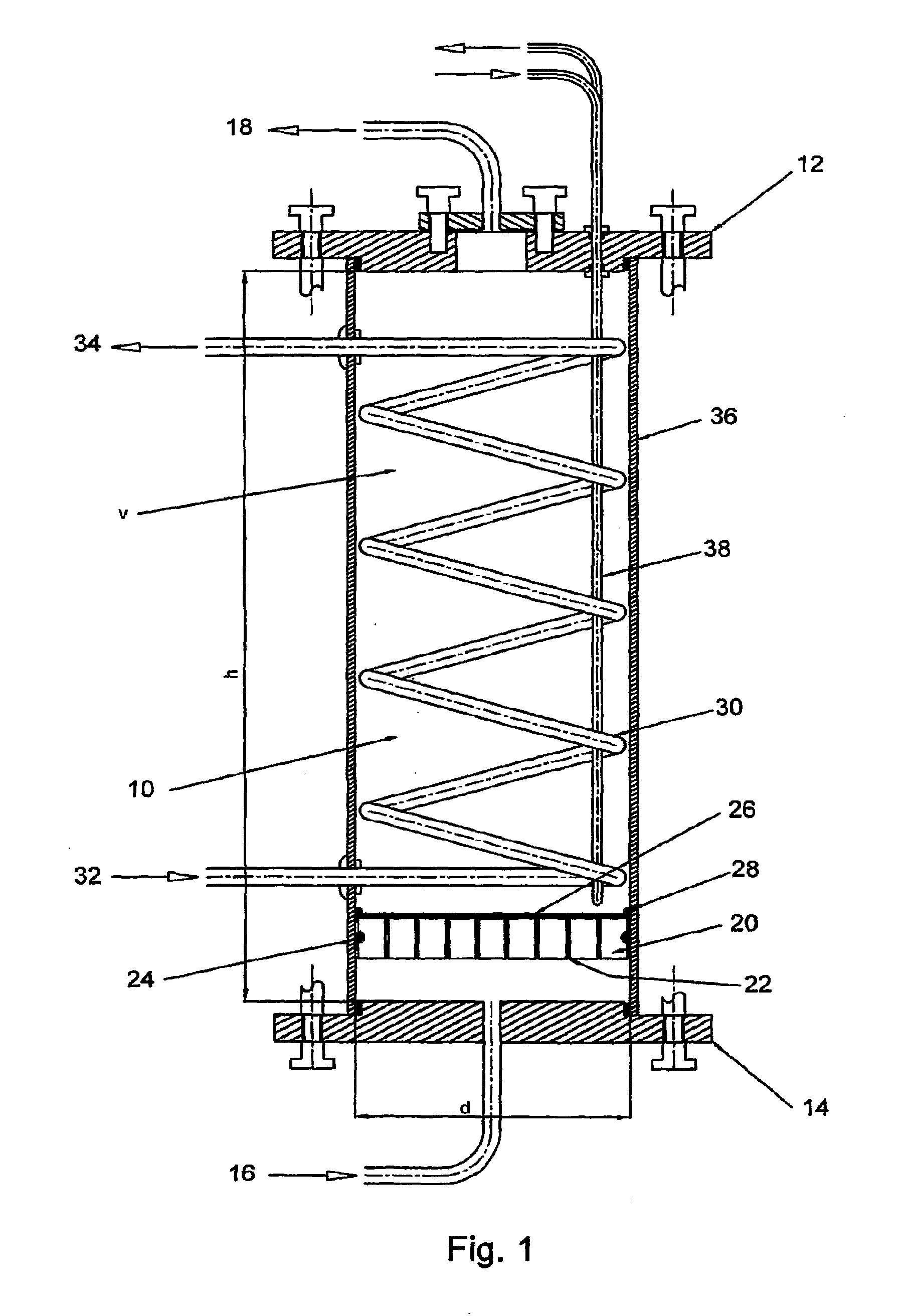
[0125]The invention provides a “functionally modular” chamber in which epithelial cells, e.g. liver cells, can be housed and manipulated through various “development / life cycle” stages. Thus, for example, liver cells can serially be: •Cultured to performance competence;[0126]Cryopreserved; and[0127]Utilized

in the same chamber, by for example, changing “solutions” and altering “conditions”.

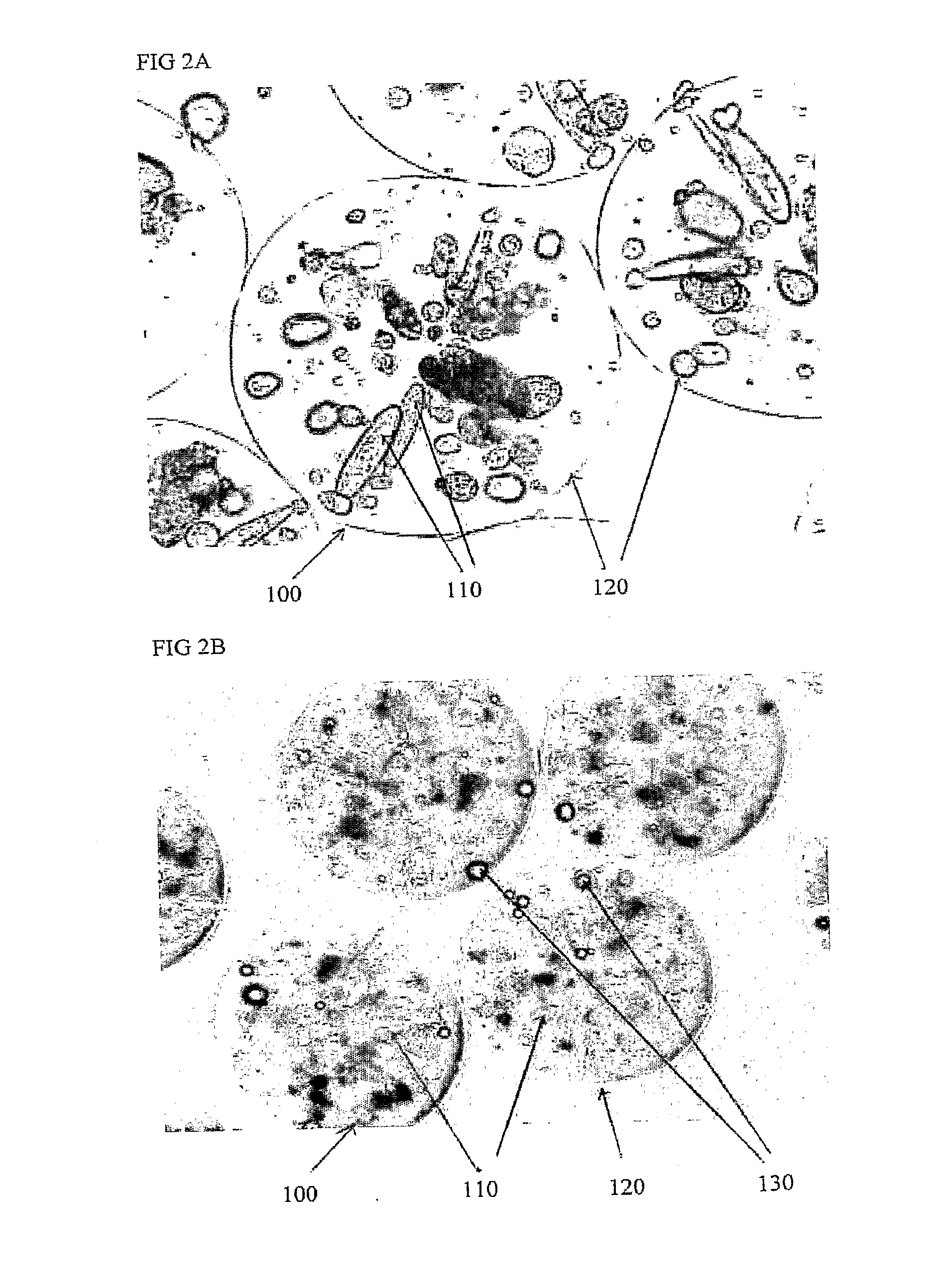
[0128]Thus, for example, a biological component, such as, alginate beads containing liver cells, may be prepared and delivered into the “functionally modular” chamber in which:[0129]Initial proliferation to optimal cell mass and performance take place;[0130]Subsequent cryopreservation can occur, and following transportation to a sick patient, and after thawing,[0131]the cells can be perfused, in-line, in the same chamber in an extracorporeal circuit attached to the patient.

[0132]Thus, whilst the chamber (section 1.0) is central to the invention a biological component (section 2.0) is also required ...


PUM

PropertyMeasurementUnit
working volumeaaaaaaaaaa
pore sizesaaaaaaaaaa
volumeaaaaaaaaaa

Abstract

The present invention relates to the field of extracorporeal liver perfusion and, more particularly, to the design of a chamber in which a biological component can be housed to form e.g. a bio-artificial liver (BAL). It also relates to a bio-artificial liver per se, it's components and methodological steps associated with its development and use. The chamber (10) for the biological component (100) of a bio-artificial liver (200) is configured to allow: •Proliferation of the biological component, in situ; •Cryopreservation of the biological component, in situ, and •Perfusion of the biological component, in situ.

Description

CROSS-REFERENCES TO RELATED APPLICATION[0001]This application is a continuation application of U.S. patent application Ser. No. 12 / 667,323, filed on Jan. 31, 2011, which claims priority to International Patent Application PCT / GB2008 / 002227, which claims priority to European application GB 0713595.7, filed Jul. 6, 20007, each of which are hereby incorporated by reference in their entirety.TECHNICAL FIELD[0002]The present invention relates to the field of extracorporeal liver perfusion and, more particularly, to the design of a chamber in which a biological component can be housed to form e.g. a bio-artificial liver (BAL). It also relates to a bio-artificial liver per se, it's components and methodological steps associated with its development and use.BACKGROUND OF THE INVENTION[0003]Currently, the sole cure for both acute and chronic liver disease and liver failure is transplantation. However, this treatment is restricted by a lack of donor organs. In the US alone, 17,000 patients ar...

Claims


Application Information

Patent Timeline
03 Nov 2016
Publication
US20160316742A1
IPC
A01N1/02; A61M1/34; C12M1/02; C12M3/00; C12M1/12; C12M1/00; A61F2/02; A61M1/36; C12N5/071
CPC
A01N1/0247; A61F2/022; A61M1/3489; A61M1/3689; C12M41/24; A01N1/0257; C12M21/08; C12M23/06
Inventors
SELDEN, CLARE; HODGSON, HUMPHREY