
Heat sink

Active Publication Date: 2016-11-03
JNC CORP
View PDF0 Cites 28 Cited by
  • Summary
  • Abstract
  • Description
  • Claims
  • Application Information

AI Technical Summary

Benefits of technology

The invention is a heat sink made of lightweight material that features a strong bond between a metal layer and a graphite layer, excellent heat-dissipation performance, and mechanical strength. It can be used in electronic equipment and batteries to prevent overheating and achieve weight reduction.

Problems solved by technology

If the weight of the thermal conductor increases, transport of the electronic equipment is liable to become difficult, and simultaneously an excessive load is liable to be applied to the CPU in which the thermal conductor is installed.
Moreover, the increase of weight of the thermal conductor to be mounted in an automobile or the like results in deterioration of fuel consumption.

Method used


Image

  • Heat sink
  • Heat sink
  • Heat sink

Examples


example 1

Preparation of Heat Sink

[0233]In a 200 mL three-necked flask, 80 g of cyclopentanone was put, a stirring blade made of fluorocarbon resin was set from above, and the stirring blade was rotated by a motor. A speed of revolution was timely adjusted according to viscosity of a solution. In the flask, 10 g of polyvinyl formal resin (PVF-K) was put using a glass funnel. PVF-K attached onto the funnel was washed with 20 g of cyclopentanone, and then the funnel was removed and a glass stopper was placed thereon. The obtained solution was heated in a water bath set at 80° C. for 4 hours while the solution was stirred to completely dissolve PVF-K in cyclopentanone. The flask after stirring was removed from the water bath to obtain a composition for forming an adhesive layer.

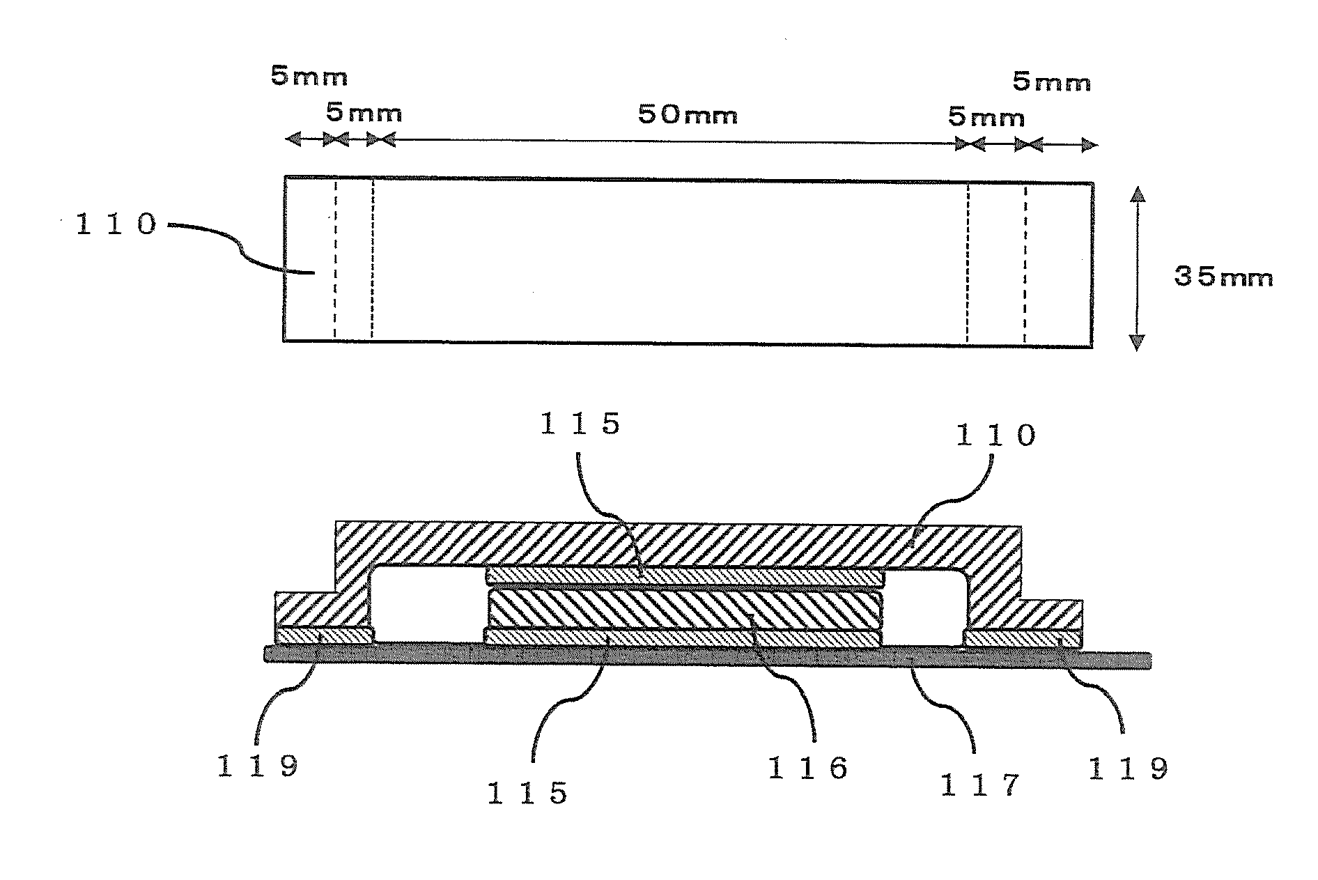
[0234]The composition for adhesive layer formation was applied onto electrolytic copper foil having a size of 300 mm×50 mm and a thickness of 0.012 mm to be 2 μm in a thickness of an adhesive coating film to be obtained, ...

example 2

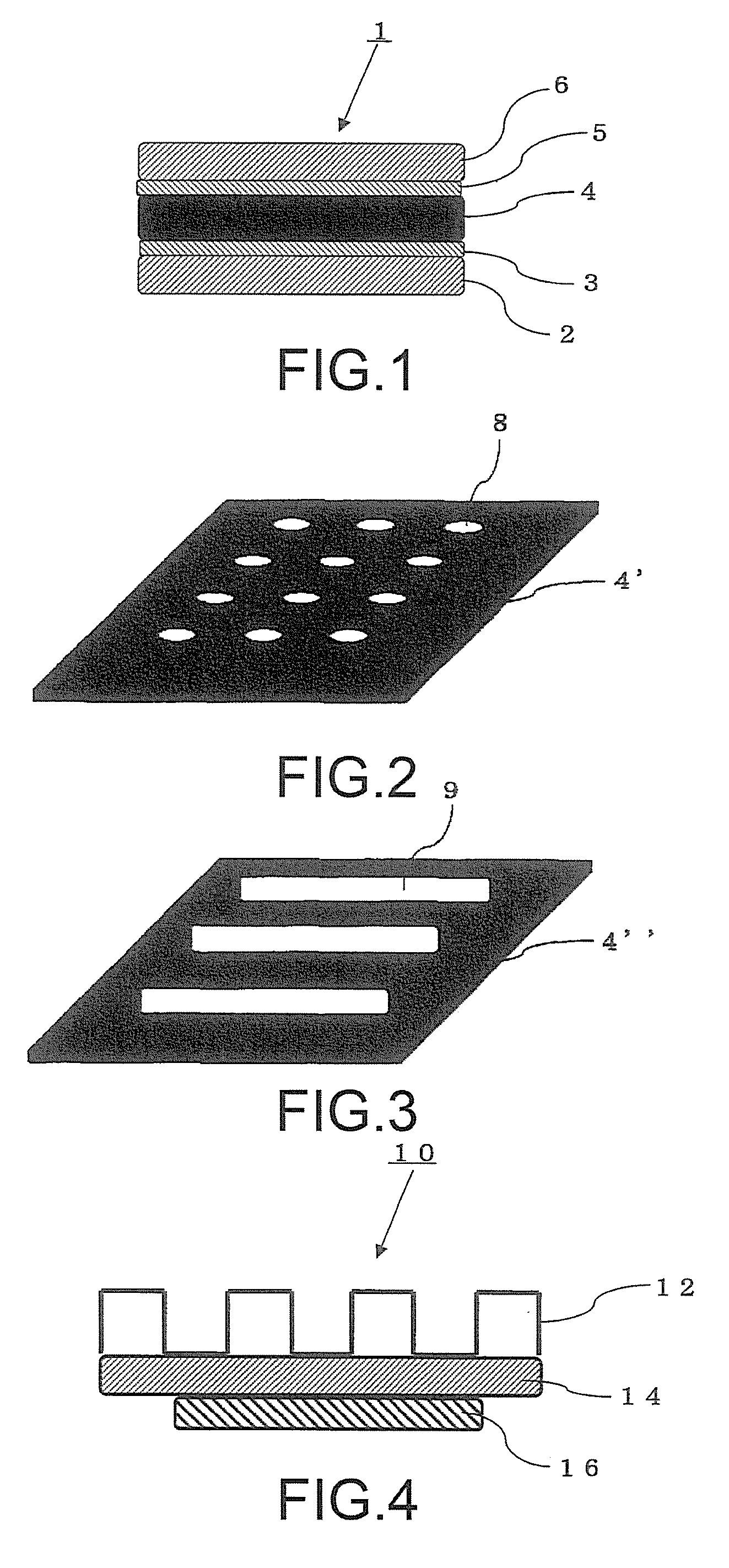
[0239]A heat sink was prepared, and heat-dissipation characteristics were evaluated in a manner similar to the method in Example 1 except that the copper pipe having the diameter of 5 mm was changed to a 5 mm-square copper square material, and a bending part was formed into a U shape as shown in FIG. 4.

example 5

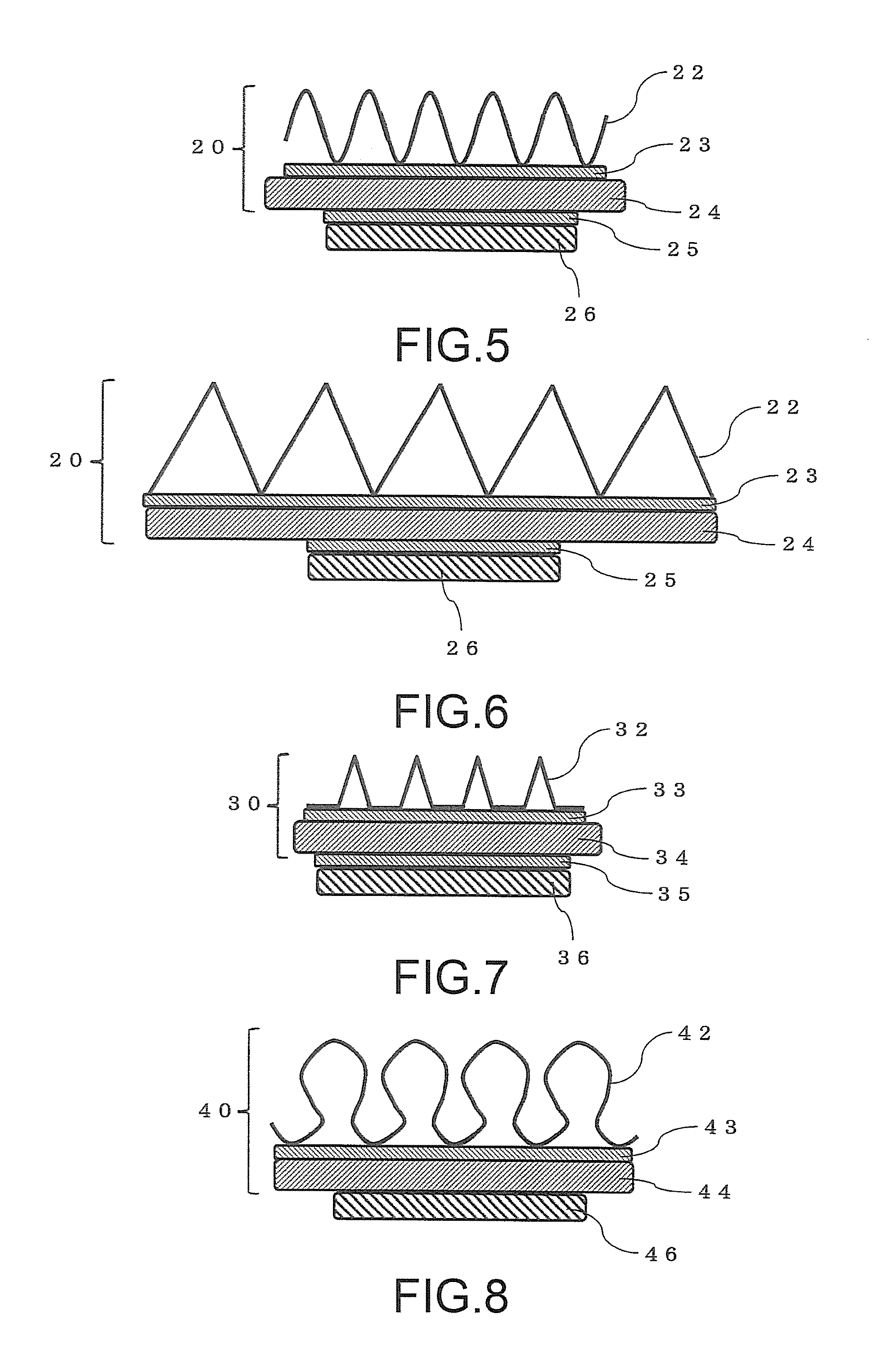
[0246]A laminate was prepared in a manner similar to Example 2 except that aluminum foil having a size of 100 mm×30 mm and a thickness of 0.02 mm and a natural graphite sheet having a size of 100 mm×30 mm and a thickness of 0.076 mm were used in place of the copper foil and the artificial graphite sheet in Example 2, and a heat-dissipating section was prepared by bending the laminate into a bellows shape to be approximately 30 mm in length in a manner similar to Example 2. A heat sink was prepared by sticking the heat-dissipating section on a magnesium sheet having a dimension of 30 mm×30 mm×1.2 mm by using a pressure sensitive adhesive tape (NeoFix10), and heat-dissipation characteristics were evaluated in a manner similar to Example 2.


PUM

PropertyMeasurementUnit
Thicknessaaaaaaaaaa
Heataaaaaaaaaa

Abstract

A heat sink, including a base section in contact with a heating unit, and a heat-dissipating section for dissipating heat received from the heating unit by the base section, in which the base section includes at least one metal layer, and the heat-dissipating section includes a laminate prepared by laminating a metal layer and a graphite layer through an adhesive layer formed by using a composition containing a polyvinyl acetal resin, or a heat sink for dissipating heat from a heating unit, in which the heat sink includes a laminate prepared by laminating a metal layer and a graphite layer through an adhesive layer formed by using a composition containing a polyvinyl acetal resin, and is arranged so as to cover the heating unit.

Description

TECHNICAL FIELD[0001]The present invention relates to a heat sink for dissipating heat from a heating unit.BACKGROUND ART[0002]In a heating element to be mounted in electronic equipment including a computer, a heating value has increased in association with achievement of high performance. For example, the heating value is particularly large in a central processing unit (CPU) mounted in the electronic equipment, and therefore a thermal conductor such as a heat sink is generally installed in the CPU. In the thermal conductor, weight increases according to achievement of size increase the like for responding to increase of the heating value in association with achievement of high speed of the CPU. If the weight of the thermal conductor increases, transport of the electronic equipment is liable to become difficult, and simultaneously an excessive load is liable to be applied to the CPU in which the thermal conductor is installed. Moreover, the increase of weight of the thermal conducto...

Claims


Application Information

Patent Timeline
IPC IPC(8): H05K7/20
CPCH05K7/2039H01L23/36H01L23/373H01L23/367H01L23/3672H01L23/42H01L23/552H01L24/33H01L2924/0002B32B9/007B32B9/045B32B15/082B32B2307/302B32B2307/54B32B2457/00H01L2924/00
Inventor FUJIWARA, TAKESHI
Owner JNC CORP
Features
  • Generate Ideas
  • Intellectual Property
  • Life Sciences
  • Materials
  • Tech Scout
  • Unparalleled Data Quality
  • Higher Quality Content
  • 60% Fewer Hallucinations
Learn More