
Downhole fluid properties analysis device and tools comprising such a device

Active Publication Date: 2016-11-10
OPENFIELD
View PDF8 Cites 5 Cited by
  • Summary
  • Abstract
  • Description
  • Claims
  • Application Information

AI Technical Summary

Benefits of technology

The invention allows for the flexible adjustment of optical path lengths from a few tens of microns to several tens millimeters. This provides a more flexible and precise method for controlling optical properties, which can be useful in various applications.

Problems solved by technology

Further, there are also the space and power constraints associated to downhole tools deployment.
Furthermore, there is the high shocks environment associated to wireline or drilling operations.
The drawbacks of such conventional sapphire windows approach are the following:Low performance of compositional analysis—The optical path length selection (light travel distance inside the fluid) is constrained by the fluid flow restriction that can be accepted without altering the sampling process and / or the representativeness of the fluid sample present in between the two windows.
Distance between windows below 1 mm is in practice impossible to implement and typical optical path lengths for current commercial tools are within the 3-5 mm range.
This limitation has forced engineers to favor analysis in the visible—near infrared spectrum where attenuation factors in hydrocarbon fluids are relatively low, despite the fact that absorption peaks are related to overtones of the vibration modes of the molecules to be detected and suffer from peak enlargements and overlaps from different compounds.
This leads to complex interpretation and relatively poor robustness and performance of compositional analysis.Optical cell contamination—Relatively large optical window surface (several mm2) and even more importantly its large curvature ratio (superior to 1 mm) favor the formation of droplets of fluids sticking on the window surface and altering analysis.Complex and expensive hardware—The window assembly (the conventional method is sapphire disk or tube brazing onto metal) is critical in order to withstand high pressure and high temperature.Optical path—The optical path length is fixed and can only be changed at the manufacturing step of the cell.Cleaning—The complex mechanical configuration of the cell flow line and windows leads to dead volumes which make the cleaning of the cell flow line during the early phase of the sampling a critical step.

Method used


Image

  • Downhole fluid properties analysis device and tools comprising such a device
  • Downhole fluid properties analysis device and tools comprising such a device
  • Downhole fluid properties analysis device and tools comprising such a device

Examples


first embodiment

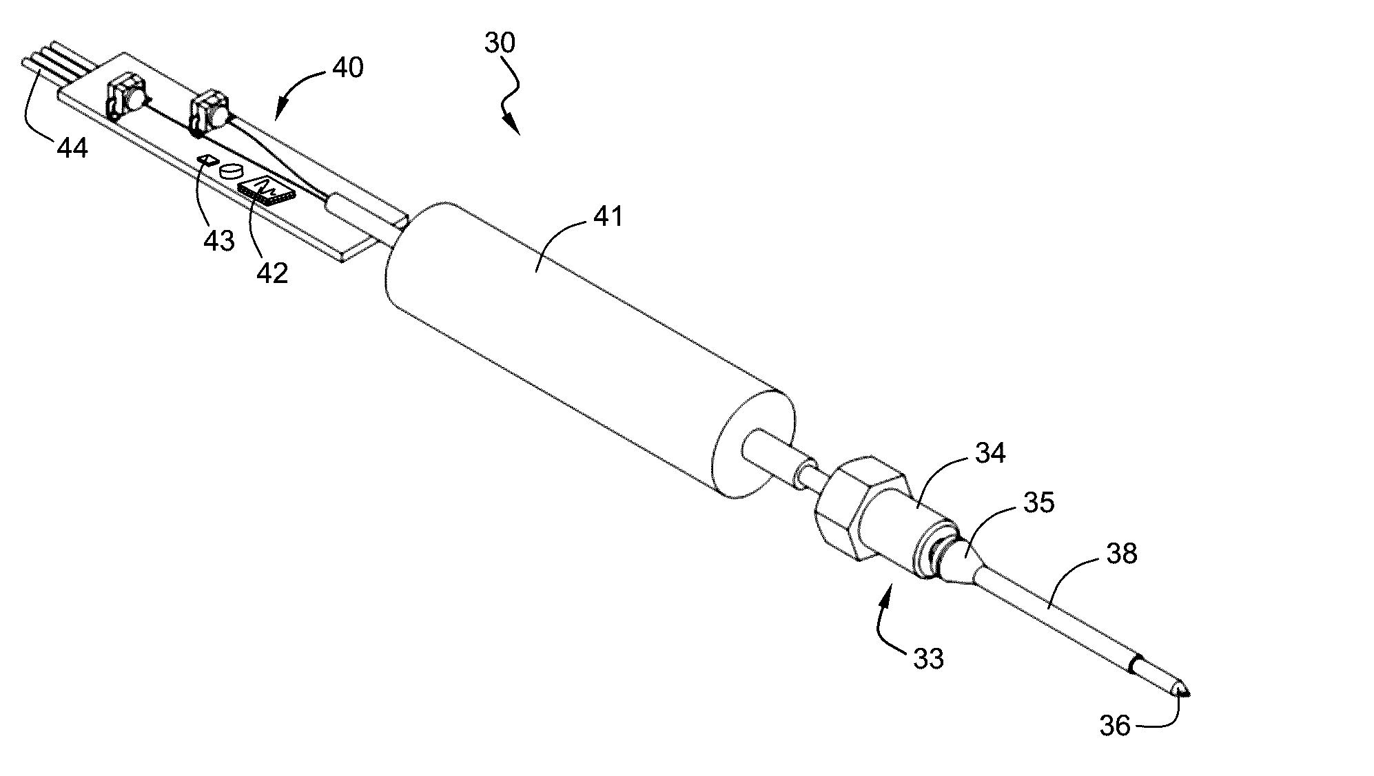
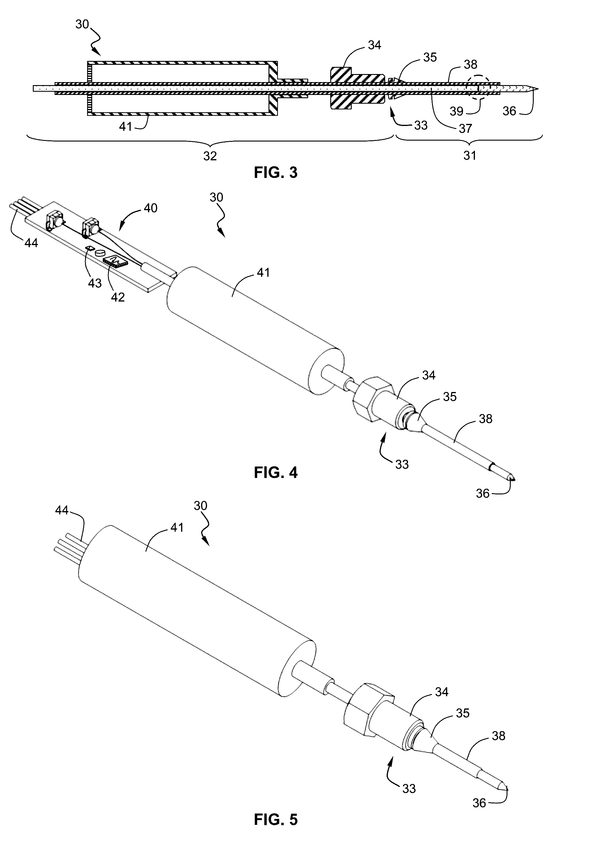
[0046]FIGS. 6 and 7A are cross section and perspective exploded views showing a downhole fluid analysis tool 50 comprising a downhole fluid analysis cell 51. The downhole fluid analysis cell 51 is connected to the downhole sampling flow line 8 by means of appropriate connectors 59. The downhole fluid analysis cell 51 comprises an analysis pipe portion 52, and first and second threaded holes 53A, 53B. The analysis pipe portion 52 is a cylindrical cavity extending along a longitudinal axis XX′ of the downhole fluid analysis cell 51 and having dimension similar to the downhole sampling flow line 8. The longitudinal axis XX′ substantially corresponds to the fluid flow 3 direction in the downhole sampling flow line 8. The first and second threaded hole 53A, 53B faces each other positioned transversally relatively to the longitudinal axis XX′ of the downhole fluid analysis cell 51. A first optical sonde 30A is inserted into the first threaded hole 53A and tightly connected by means of the...

second embodiment

[0052]The second embodiment enables having the optical probes inserted along the length of the downhole fluid analysis cell 51. This configuration allows a wider optical path length control and is also more adapted to packaging inside a tube shaped tool like a formation tester tool.

[0053]The distance between the tips 36A and 36 B of the optical probes in order to define the optical path length 56 is selected according to attenuation factors to be measured. The attenuation factor may range from several orders of magnitude which require an optical path length from a few tens of microns to a few tens of millimeters depending on fluid composition and light wavelengths. The invention enables a fine definition of the optical path length 56 by sliding the optical probe into the threaded holes 53A, 53B as hereinbefore described.

[0054]FIGS. 9-11 illustrate a particular implementation of the downhole fluid analysis cell 51 that is particularly well adapted for integration in a wireline format...


PUM


Abstract

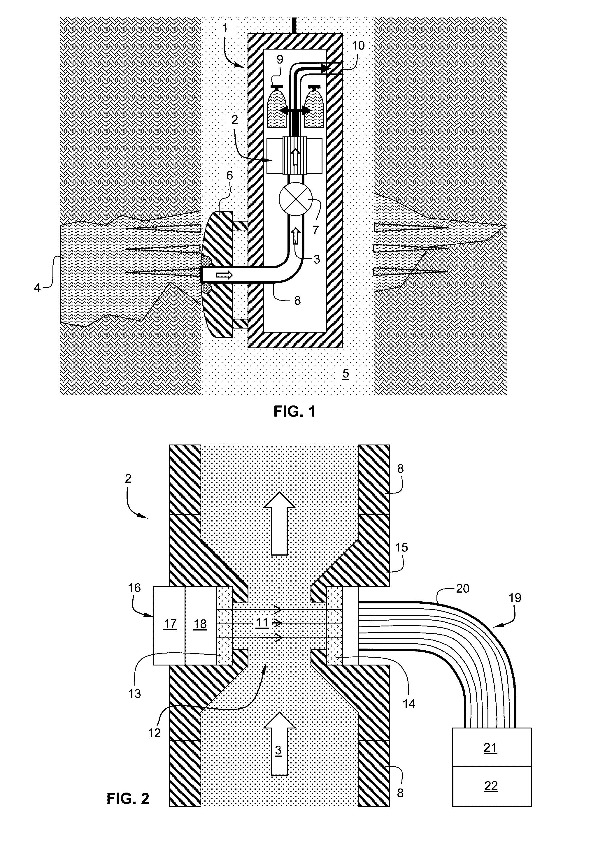
A downhole fluid properties analysis device (51) is connectable to a downhole sampling flow line (8). The downhole sampling flow line (8) has an internal diameter between 2 to 15 mm adapted to let flow the fluid (3) to be analyzed. The fluid (3) is a hydrocarbon multiphase fluid mixture from a hydrocarbon subsurface reservoir (4). The downhole fluid properties analysis device (51) comprises:an analysis pipe portion (52); anda first optical probe and a second optical probe (30, 30A, 30B, 70), the first optical probe being a light emitting probe adapted to be coupled to a light source and arranged to transmit a light into the fluid (3), and the second optical probe being a light receiving probe adapted to be connected to a spectrometer and arranged to produce a signal resulting from an interaction of the fluid with said light indicative of the downhole fluid properties;Each of said optical probes (30, 30A, 30B, 70) comprises an elongated body mounted through the wall of the analysis pipe portion in a sealed manner and having a tip (36, 36A, 36B, 72), the tip being needle shaped and having an external diameter less than 1 mm. The first tip of the first optical probe and the second tip of the second optical probe (30, 30A, 30B, 70) project into a flow section of the analysis pipe portion such that the first tip (36A, 72) faces the second tip (36B) at a defined distance ranging from 10 μm to 99 mm.

Description

TECHNICAL FIELD[0001]The invention relates to a downhole fluid properties analysis device and a downhole fluid analysis tool comprising such a fluid properties analysis device. The invention is particularly applicable to the analysis of a multiphase fluid mixture flowing from a hydrocarbon bearing zone into a hydrocarbon well by means of a formation tester tool that operates at downhole pressure and temperature conditions. The invention applies to the analysis of the optical properties of such fluid flowing in downhole sampling flow lines of small dimension (millimeters range) of the formation tester tool. The invention is particularly applicable to the characterization in real time of hydrocarbon reservoir fluids (e.g. crude oil, gas, brines).BACKGROUND[0002]The documents U.S. Pat. No. 4,994,671, US2014 / 0361155 and the Technical Paper “Advanced Downhole Fluid Analysis” IBP3075_10 of Rio Oil & Gas Expo and Conference 2010 held 13-16 Sep. 2010 in Rio de Janeiro presented by Brazilian...

Claims


Application Information

Patent Timeline
IPC IPC(8): G01V8/20E21B49/08
CPCG01V8/20E21B49/082G01N2201/06113G01N21/31E21B49/10E21B49/08G01V8/02G01V8/12G01N21/68G01N21/8507G01N33/2823E21B47/113E21B47/10G01N27/08
Inventor DONZIER, ERICABBASSI, LINDATAVERNIER, EMMANUEL
Owner OPENFIELD
Learn More