Electric motor control device

a technology of electric motors and control devices, which is applied in the direction of electric motor control, electric commutation motor control, dynamo-electric components, etc., can solve the problems of small loss generated by power conversion from dc power to ac power, loss at the time of start-up, and noise generation of switching elements, so as to suppress noise generation, reduce power loss, and suppress the effect of temperature rise of switching elements

Active Publication Date: 2016-11-10
MITSUBISHI ELECTRIC CORP
View PDF1 Cites 7 Cited by
  • Summary
  • Abstract
  • Description
  • Claims
  • Application Information

AI Technical Summary

Benefits of technology

[0012]According to an electric motor control device of the present invention, there can be obtained an electric motor control device which suppresses cost-up and the generation of a noise, reduces a power loss caused by a switching operation of switching elements even when an electric motor is equal to or less than a predetermined rotational number (for example, an unrotatable or extremely low rotational state) to suppress a temperature rise of the switching elements, and can generate driving force corresponding to a driver's operation.
[0013]The foregoing and other objects, features, and advantageous effects of the present invention will become more apparent from detailed description in the following embodiments and description in the accompanying drawings.

Problems solved by technology

There exist a loss at the time of start-up, an ON loss, and a loss at the time of start-up / stop in the switching operation of the switching elements.
Accordingly, the switching operation is small means that a loss generated by power conversion from DC power to AC power is small.
However, the power conversion from the DC power to the AC power is the switching operation at high frequency and high power; and accordingly, the switching element generates heat by a loss (switching loss) generated by the switching operation and the temperature of the switching element rises.
Then, when the switching element reaches its upper limit temperature, supply power to the electric motor is reduced is order to avoid a breakdown of the switching element and, more specifically, the number of switching is reduced and it becomes difficult to supply desired power, which is for generating driving force corresponding to a driver's operation, to the electric motor.

Method used


Image

  • Electric motor control device
  • Electric motor control device
  • Electric motor control device

Examples


embodiment 1

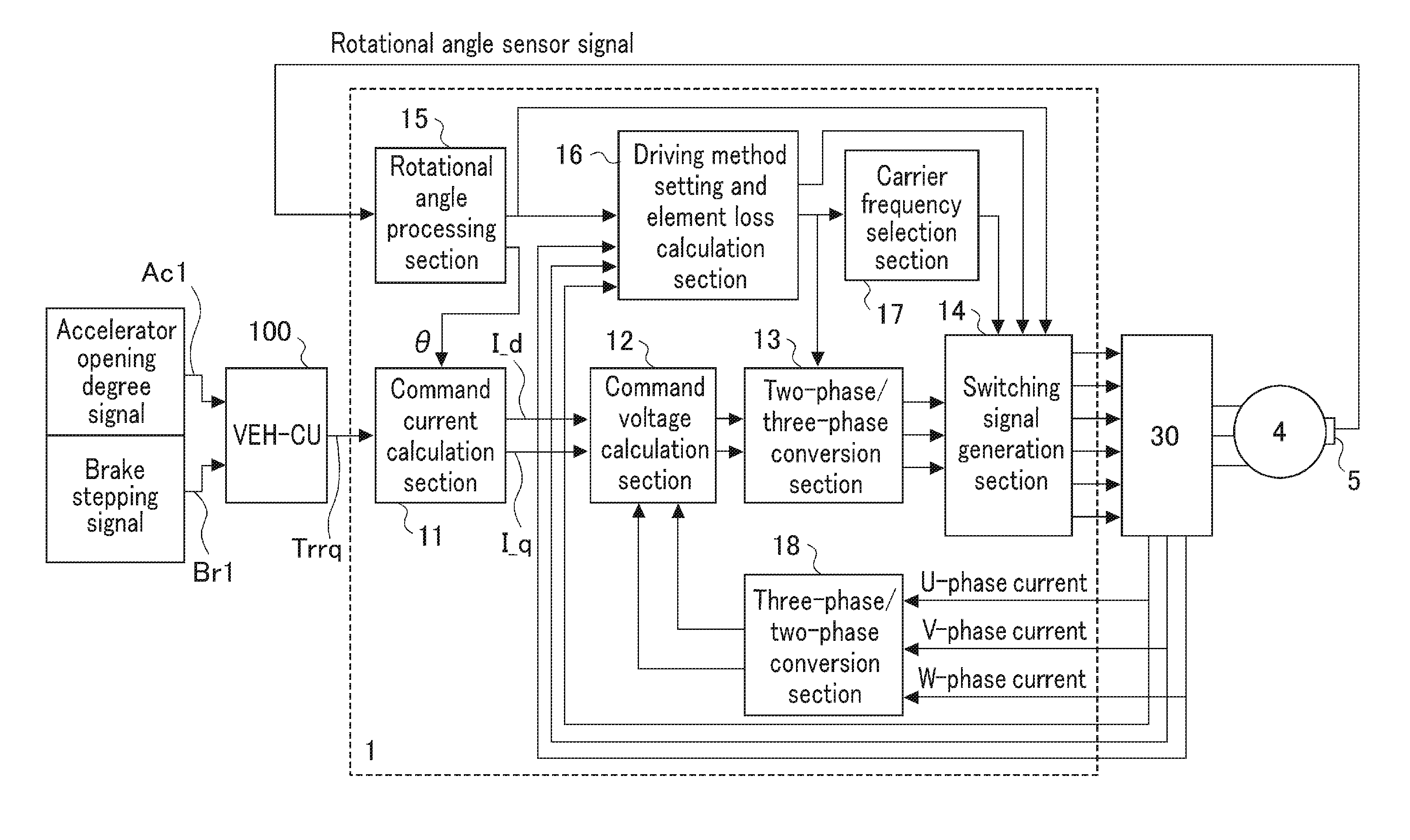
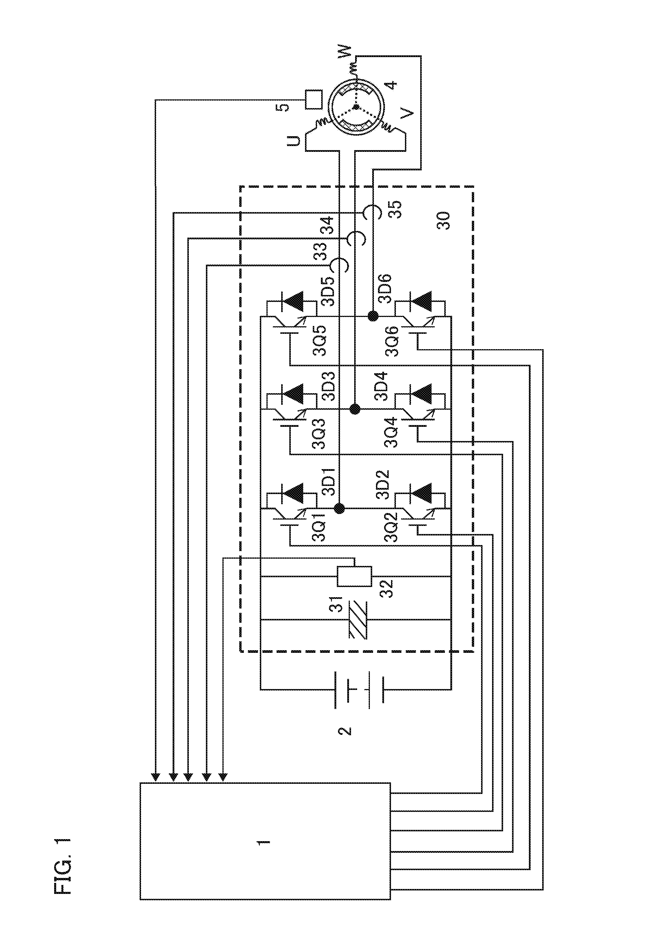
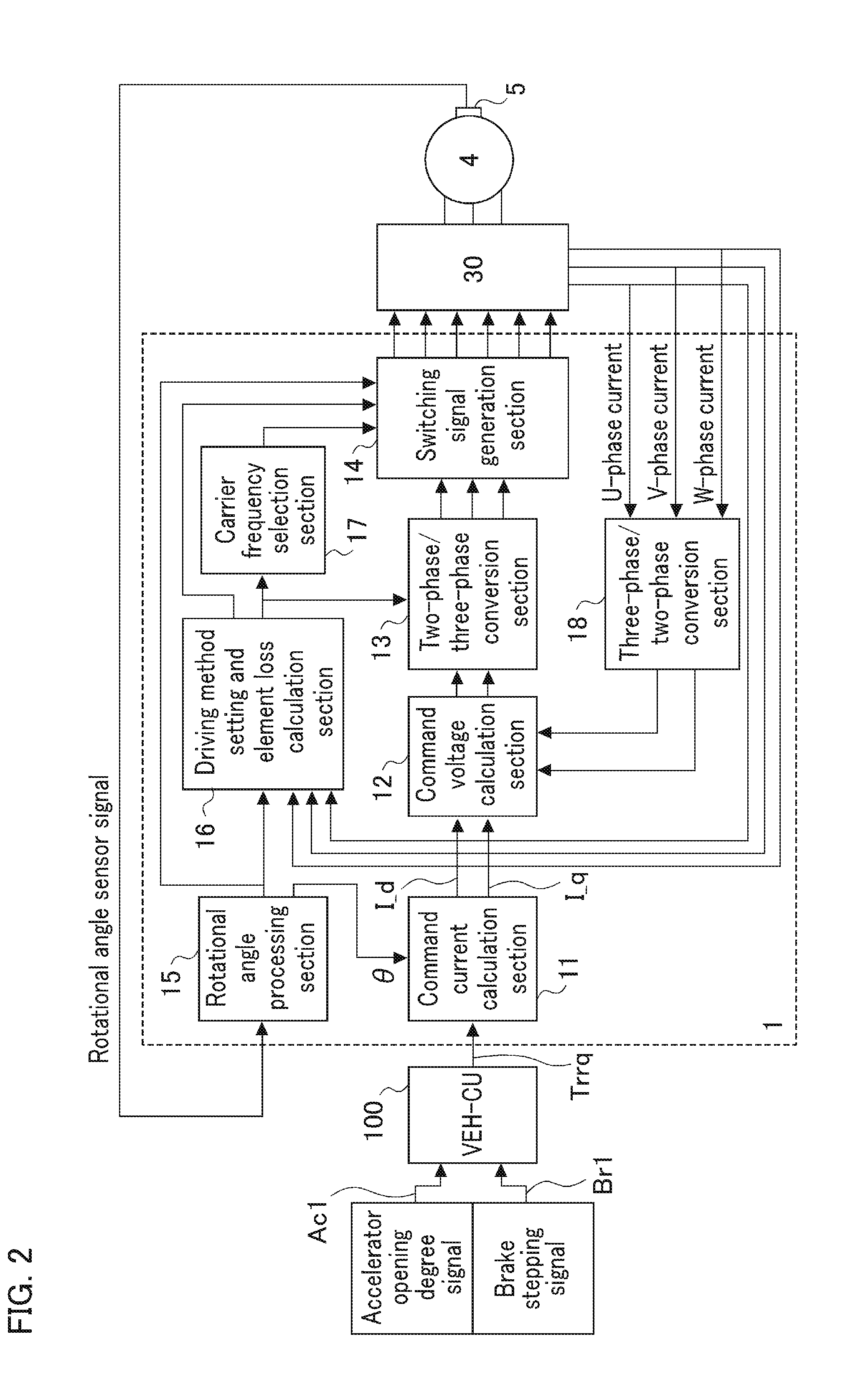
[0028]FIG. 1 is a diagram showing the entire configuration of an electric motor control device provided with a power converter in Embodiment 1 of the present invention. In FIG. 1, reference numeral 1 denotes a motor control unit (referred to as an “MCU”) which is a control unit that controls a driving method of the power converter and the like according to the present invention; 2, a battery that supplies DC power; 30, a power converter (also referred to as an “inverter”) which is provided in parallel with the battery 2 and converts the DC power from the battery 2 into AC power; and 4, an electric motor which generates driving force by the AC power from the inverter 30 to drive rotation. The electric motor 4 is connected to vehicle's wheels (not shown in the drawing) via a power transmission mechanism (not shown in the drawing). Furthermore, 5 denotes a rotational angle sensor that outputs a signal according to the rotation of the electric motor.

[0029]The inverter 30 includes a smoo...


PUM


Abstract

An electric motor control device drives a power converter (30) by two-phase modulation drive based on calculation of a driving method setting and element loss calculation section (16) when an electric motor (4) is equal to or less than a predetermined rotational speed; and switches switching signals from a switching signal generation section (14) to switch a switching operation of the switching elements when a loss integrated value of a first switching element with a large switching loss or a second switching element exceeds a predetermined value.

Description

TECHNICAL FIELD[0001]The present invention relates to electric motor control devices and, more particularly, relates to an electric motor control device which changes a driving method of a power converter according to an operation state of an electric motor.BACKGROUND ART[0002]In recent years, with the aim of reducing the amount of carbon dioxide emissions and improving fuel consumption, there has become widespread vehicle mounted with an electric motor and an internal combustion engine, that is, a hybrid vehicle and / or an electric car which is mounted with only an electric motor and drives by the driving force of the electric motor. In these vehicles mounted with the electric motors, there are mounted with a charging device which outputs direct current (DC) power, a power converter (inverter) which converts the DC power from the charging device into alternating current (AC) power and supplies the power to the electric motor, and the like, in addition to the electric motor.The power...

Claims


Application Information

Patent Timeline
Patent Type & Authority Applications(United States)
IPC IPC(8): H02P29/68H02P6/06H02K11/26H02K11/27H02P27/08H02K11/21
CPCH02P29/68H02P27/08H02P6/06H02K11/26H02K11/27H02K11/21H02P27/085H02P6/00H02P23/00H02P6/32
Inventor SHODA, TOMOHISAOGAWA, YASUFUMINISHIJIMA, YOSHIMASA
Owner MITSUBISHI ELECTRIC CORP
Why Eureka
Try Eureka