
Local Oscillator Signal Generation

a local oscillator and signal technology, applied in low noise amplifiers, baseband system details, line-faulst/interference reduction, etc., can solve the problem of degrading the signal-to-noise ratio of the wanted signal, the spectral impurity of the local oscillator signal can be particularly severe, and the single receive chain described above may not be suitable for contiguous or non-contiguous intra-band ca

Inactive Publication Date: 2016-11-10
TELEFON AB LM ERICSSON (PUBL)
View PDF9 Cites 7 Cited by
  • Summary
  • Abstract
  • Description
  • Claims
  • Application Information

AI Technical Summary

Benefits of technology

This patent describes a wireless transceiver that can reliably and power-efficiently operate using digital circuitry. It includes a quadrature generation stage that uses differential amplifiers to deliver a high-level source signal to the generation stage. The differential amplifiers help reduce common-mode signals and intermodulation products, resulting in a cleaner signal for improved performance. The transceiver also allows for flexibility over the choice of carriers for carrier aggregation without prohibiting certain frequencies. Overall, this patent provides a solution for improving the quality and efficiency of wireless communication.

Problems solved by technology

A spurious signal at such a frequency can, in a receiver having a direct-conversion architecture, result in an unwanted or interfering signal at RF, having the same frequency as the spurious signal, being down-converted into the range of frequencies occupied by the down-converted wanted signal, thereby degrading the signal-to-noise ratio of the wanted signal.
Such a problem of spectral impurity of the local oscillator signals can be particularly severe in a receiver employed for carrier aggregation.
In general, the single receive chain described above may not be suitable for contiguous or non-contiguous intra-band CA.
For example, a single receive chain is not suitable for non-contiguous intra-band CA if a blocking signal is present between the non-contiguous wanted channels and has a power level that cannot be tolerated by the analogue and / or digital signal processing circuits of the receive chain.

Method used


Image

  • Local Oscillator Signal Generation
  • Local Oscillator Signal Generation
  • Local Oscillator Signal Generation

Examples


Embodiment Construction

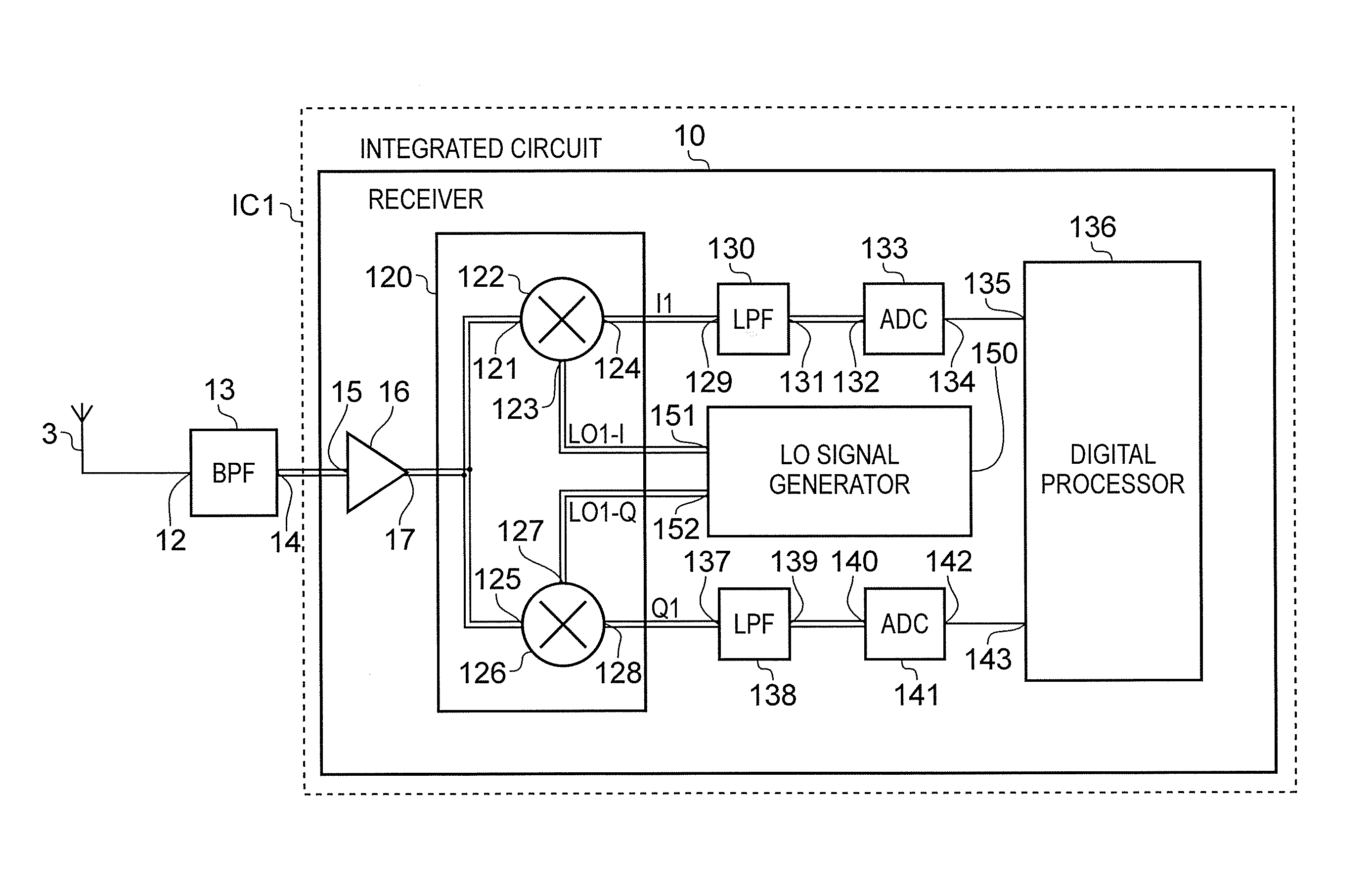
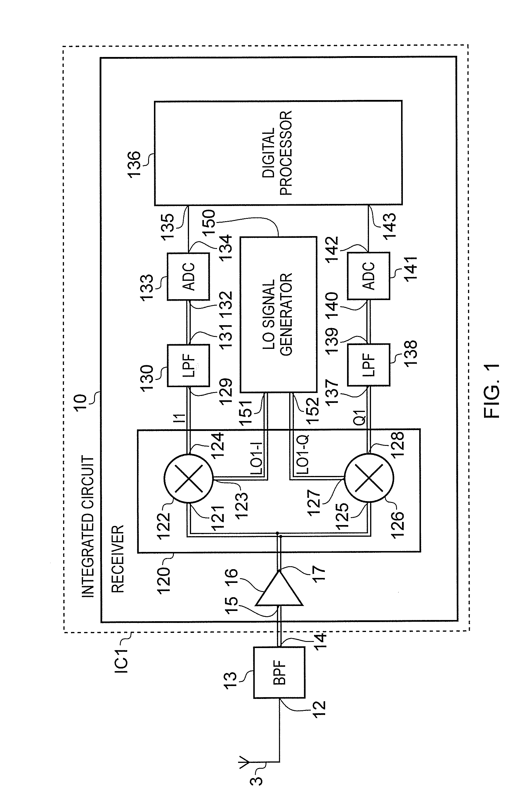
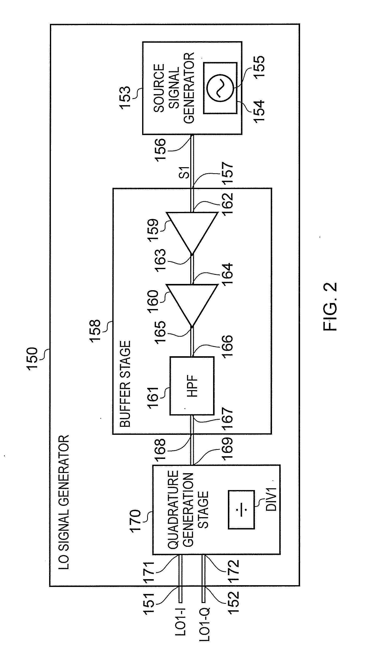
[0009]According to a first aspect there is provided a local oscillator signal generation circuit comprising:

[0010]a source signal generator arranged to generate a differential-mode source signal;

[0011]a buffer stage coupled to an output of the source signal generator and arranged to buffer the differential-mode source signal;

[0012]a quadrature generation stage coupled to an output of the buffer stage and arranged to generate an in-phase local oscillator signal and a quadrature local oscillator signal from the buffered differential-mode source signal,

[0013]wherein the buffer stage comprises:

[0014]a primary differential amplifier having an input coupled to an input of the buffer stage, and

[0015]a secondary differential amplifier having an input coupled to an output of the primary differential amplifier and an output coupled to the output of the buffer stage.

[0016]According to a second aspect there is provided a method comprising:

[0017]generating a differential-mode source signal;

[0018...


PUM


Abstract

A local oscillator signal generation circuit (150) for generating quadrature-related local oscillator signals comprises a source signal generator (153) arranged to generate a differential-mode source signal, a buffer stage (158) coupled to an output (156) of the source signal generator (153) and arranged to buffer the differential-mode source signal, and a quadrature generation stage (170) coupled to an output (168) of the buffer stage (158) and arranged to generate an in-phase local oscillator signal and a quadrature local oscillator signal from the buffered differential-mode source signal. The buffer stage (158) comprises a primary differential amplifier (159) having an input (162) coupled to an input (157) of the buffer stage (158), and a secondary differential amplifier (160) having an input (164) coupled to an output (163) of the primary differential amplifier (159) and an output (165) coupled to the output (168) of the buffer stage (158).

Description

FIELD OF THE DISCLOSURE[0001]The present disclosure relates to local oscillator generation. More specifically, it relates to a local oscillator signal generation circuit, a wireless receiver and wireless transceiver comprising the local oscillator signal generation circuit, an integrated circuit comprising the wireless receiver, an integrated circuit comprising the wireless transceiver, and a method of generating local oscillator signals.BACKGROUND TO THE DISCLOSURE[0002]A radio receiver for a mobile phone may be designed to receive a radio frequency (RF) signal having a single modulated carrier at a single carrier frequency. Such a radio receiver may have a direct-conversion architecture, where a received signal is down-converted to in-phase and quadrature baseband signals, denoted I and Q respectively, using two local oscillator signals. This down-conversion is known as I / Q down-conversion. Both local oscillator signals have the same frequency, which is equal to the carrier freque...

Claims


Application Information

Patent Timeline
Patent Type & Authority Applications(United States)
IPC IPC(8): H04B1/12H04L25/08H03F3/195H04L25/02H03B27/00H03F3/45
CPCH04B1/123H03B27/00H03F3/45928H03F2200/294H04L25/0292H04L25/085H03F3/195
Inventor JUSSILA, JARKKOSIVONEN, PETESUHONEN, MARKUS
Owner TELEFON AB LM ERICSSON (PUBL)
Learn More