
Photonic sensor for in situ selective detection of components in a fluid

Active Publication Date: 2016-11-17
GENERAL ELECTRIC CO
View PDF4 Cites 11 Cited by
  • Summary
  • Abstract
  • Description
  • Claims
  • Application Information

AI Technical Summary

Benefits of technology

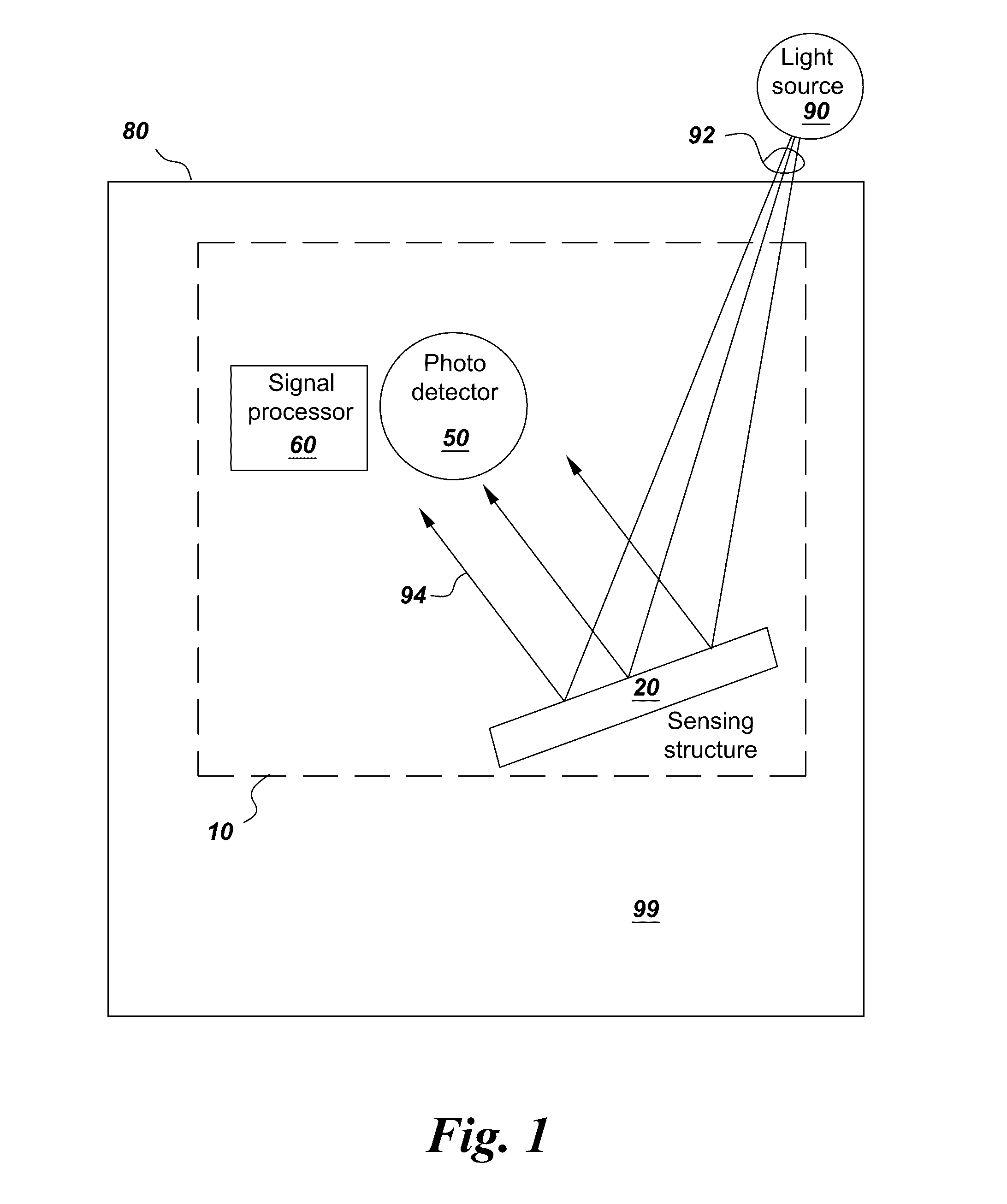
The patent is about a fluid sensor that can detect different components of a fluid based on their optical properties. The sensor consists of multiple layers that create an open-fluid resonant structure, which allows the measured fluid to interact with the sensor. The sensor can also include a polarization-sensitive photodetector to detect different components of the fluid. The method of measurement involves exposing the sensor to the fluid, interrogating it with light, measuring the change in optical properties, and correlating it to a stored value to get quantitative values of the different components in the fluid. The patent also describes a methane detection system that uses a single sensor for selective detection of methane through its open-air structure and a methane-sensing moiety integrated as a part of the sensor.

Problems solved by technology

However, serious limitations of such sensors include inability to measure some simple small molecule gases for which there are no chemical interactions available.
The significant limitation of photonic resonant vapor sensors that operate on univariate vapor quantitation principles is in their cross-sensitivity to other gases in atmosphere.
Such cross-sensitivity reduces accuracy of gas detection and increases the likelihood of false alarms that are unacceptable in demanding applications such as in situ detection of methane leaks in various equipment types e.g. gate and compressor stations, machine halls, valves, pressure relief valves, connectors, flanges, and others as well as along the pipelines.

Method used


Image

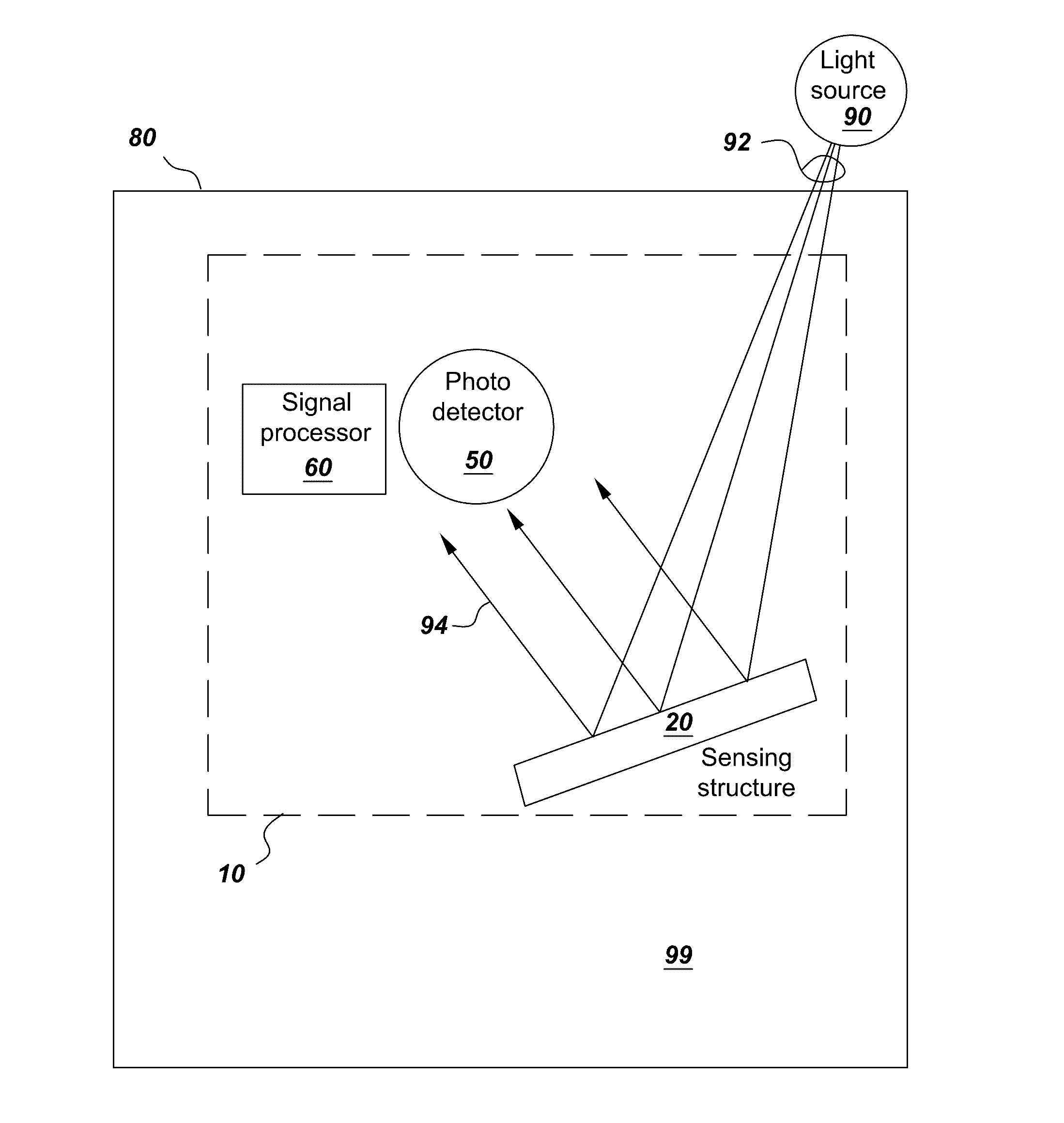
  • Photonic sensor for in situ selective detection of components in a fluid
  • Photonic sensor for in situ selective detection of components in a fluid
  • Photonic sensor for in situ selective detection of components in a fluid

Examples


examples

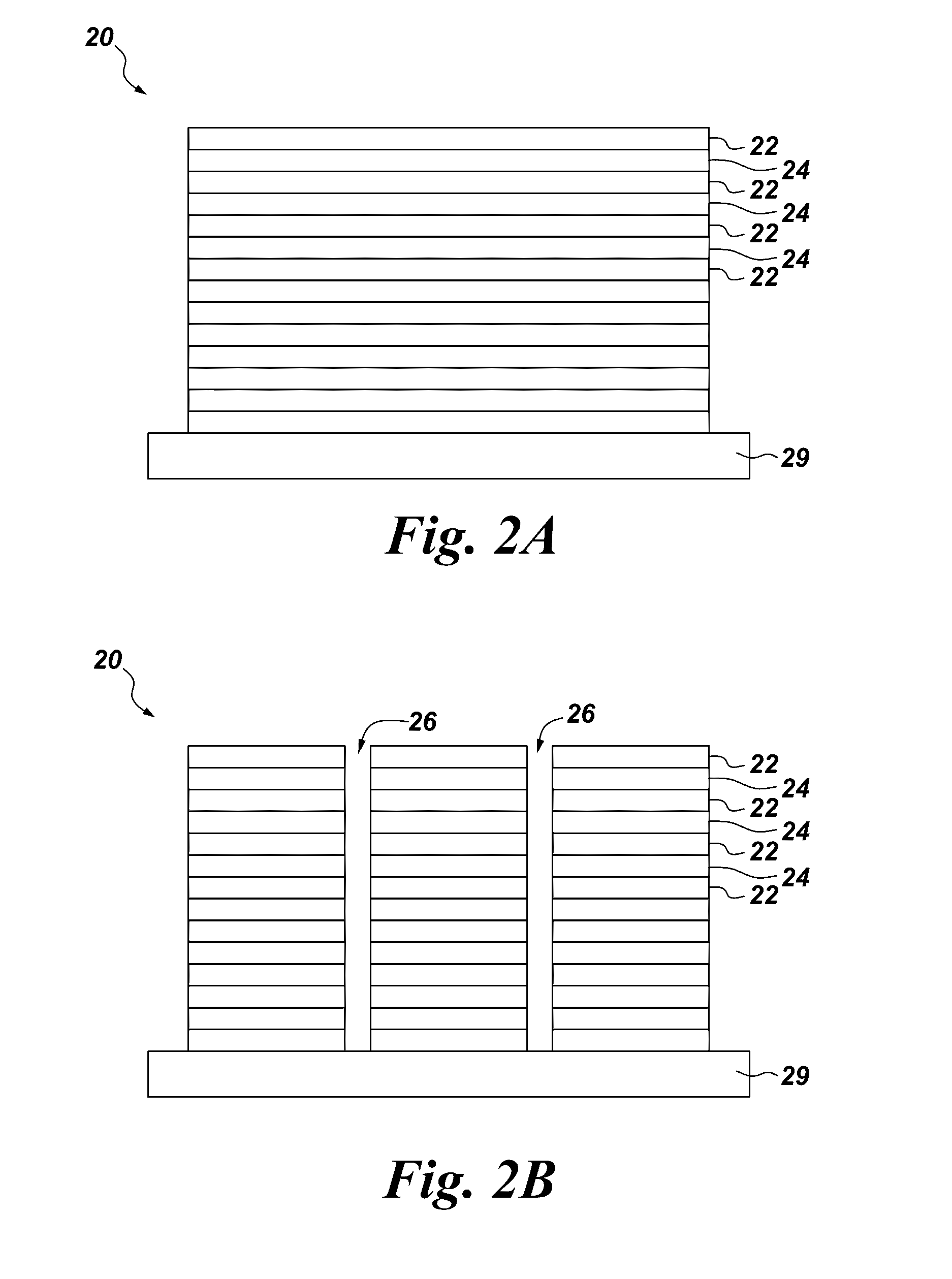
[0076]Design of a colorimetric sensor for selective detection of methane was demonstrated using two exemplary multilayer interferometric structures. These sensor structures contained five and ten interferometric layers and each layer had a small extinction coefficient of 0.02 and was sensitive to methane.

[0077]More specifically, a design of a methane sensor comprises an interferometric structure with five methane-sensitive layers, whereas a design of a methane sensor comprises an interferometric structure with ten methane-sensitive layers. Each of the layers is 207.1824 nm thick and are separated from each other by an air gap which is 100 nm thick. In this design, the width of the structure is at least 100 times larger than the thickness of the methane-sensitive layers or the air gap. The operating wavelengths for this photonic structure are in the visible spectral range.

[0078]An exemplary methane-sensing moiety (i.e. a cryptophane E) was implemented as a part of the resonant struct...


PUM


Abstract

A fluid sensor that includes fluid sensitive interferometric nanostructure layers configured into an open-air resonant structure. Another fluid sensor also includes a polarization sensitive photodetector configured to detect optical contributions of different components of a fluid to the structure. A photonic sensor system includes: a photodetector; a signal processor coupled to the photodetector; and a sensor structure configured to provide fluid-response selectivity, spatially distribute light, and to receive light from a light source and convey light to the photodetector. A method of selective measurement of components in fluid in a process area includes: exposing a sensing structure to the fluid; interrogating the sensing structure with light from outside the process area; measuring a change in optical properties of the sensing structure; correlating the measured change to a stored value; and providing quantitative values of levels of the components in the fluid.

Description

CROSS-REFERENCE TO RELATED APPLICATIONS[0001]This application claims priority to, commonly assigned, U.S. Application Ser. No. 62 / 162,156, Entitled: STRUCTURAL COLOR-BASED SENSORS FOR IN SITU SELECTIVE DETECTION OF METHANE (attorney docket no. 281860-1). The contents of which are incorporated herein by reference in its entirety.BACKGROUND[0002]The subject matter of this disclosure relates generally to sensing and, more particularly, to photonic sensors for in situ selective detection of components in fluids, such as methane in an industrial fluid.[0003]Colorimetric gas sensing is a well-established methodology known for almost a century. In colorimetric gas sensing, there are diverse forms of colorimetric sensing materials such as sensing films, sensing tapes, sensing chips, sensing fibers, and others. These and other colorimetric sensing materials operate on two different basic principles.[0004]The first principle involves chemical means of color formation by chemical dyes, pigment...

Claims


Application Information

Patent Timeline
IPC IPC(8): G01N21/25G01N21/27G01N21/29
CPCG01N21/251G01N21/29G01N2201/12G01N33/0047G01N21/27G01N21/7746G01N21/783G02B6/02095G02B6/1225G01N2021/7779G01N21/8483G01N33/1833G02B6/00G01N27/125
Inventor POTYRAILO, RADISLAV ALEXANDROVICHAHMAD, WAJDI MOHAMMADALKADI, NASRWESTERHEIDE, JOHN ANDREWKOSTE, GLEN PETERDEKATE, SACHIN NARAHARI
Owner GENERAL ELECTRIC CO
Learn More