
System and method for monitoring and controlling production of composite materials

a technology of composite materials and monitoring and control, applied in the direction of material analysis, material heat development, instruments, etc., can solve the problems of insufficient control, insufficient control, and insufficient control of production,

Inactive Publication Date: 2016-11-24
ROCK CREEK RES
View PDF7 Cites 10 Cited by
  • Summary
  • Abstract
  • Description
  • Claims
  • Application Information

AI Technical Summary

Benefits of technology

This patent is about a method of curing composite materials using a resin and fiber composite material. The method involves placing the material in a process environment and measuring the temperature while it is being cured. The method also involves using a test sample made of the same material in analytical equipment to measure the temperature and viscoelastic properties of the material. The results from the test sample are used to estimate the state of curing of the material in the process environment. The technical effect of the invention is to provide a better way of controlling the curing process of composite materials, which can enhance the quality and efficiency of the process.

Problems solved by technology

This approach has been historically adequate to build certain structures, but is costly to develop, costly to implement and yields results that are far from optimal.
This practice is expensive and ultimately loses the desirable level of control as the specifications are transferred to other activities, organizations change and time passes.
Under ideal conditions, the data generated in the laboratory are still not representative of the production environment.
Thus, even the original manufacturing process lacks accuracy when comparing the desired versus actual material state.
Unfortunately, the correlations suggested between in-situ measurements and the cure state as defined by the performance requirements of the part are often simple speculation.
Further, some of these speculations have been accepted by some and have led to incorrect and potentially dangerous interpretations of cure.
While in-situ dielectric sensors may have some utility, the failure to recognize their limitations could be catastrophic if the data derived from them are taken as the final measure of cure.
Another problem with the use of the “ionic viscosity” property cited by Wit et al. is the lack of an international standard or even a rigorous definition by which to determine when cure has taken place.
The Wit et al. reference, therefore, cannot allow changes in the remote device (test autoclave) in any way that would make it less than fully representative of the production device in all respects.
But the term “ionic viscosity” used by Wit et al. is not an actual viscosity measurement and therefore cannot be compared to an actual viscosity standard, and thus cannot be used accurately in an application where measurements of actual viscosity are critically important.
The limitations of dielectric measurements are that the correlation to mechanical properties, where it exists at all, only exists in a limited range during the cure and is subject to many sources of systematic error (such as discussed in the following Zsolnay patents).
The disadvantage is the added cost of installing the sensors and the limited value of the data generated.
Shorts caused by conductive fibers and incomplete wetting of the sensor can lead to gaps in the data and erratic responses.
These and similar sensors using sound attenuation, sound velocity and sound frequency response also exhibit problems with sensor installation, wetting by the matrix and secondary conversion of data to obtain meaningful viscoelastic material state properties.
Sensor size and placement are also problematic.
These methods require complex tooling and setup to obtain results.
The placement of these sensing systems within an autoclave or other processing environment typical of composite processing is a major task and requires a high degree of technical oversight.
The utility of these sensors is limited to materials that have spectral responses that would permit monitoring of absorption peaks critical to material performance.
Imbedding the fibers in the composite material part and making low loss optical connections create added complexity.
Handling the fibers to ensure breakage does not occur is also a problem.
Data interpretation is complex and requires skill in chemistry.
For the reasons stated, none of these methods involving prior art sensors has developed substantial use for production control because of difficulties in application and interpretation.
The process equipment and tooling present a difficult and often hostile environment for in-situ sensors and accurate measurement is not possible for many of the properties that are critical to product quality and process control.
Efforts to overcome the inadequacies of the sensor data using mathematical means further adds to the complexity of the process.
Even when the in-situ sensor can readily withstand the process conditions, there are issues of sensor placement, and the challenges of bringing the sensor leads from the tooling through the walls of processing equipment and to the device for converting the sensor signal to meaningful data.
Another problem with conventional in-situ sensors is that verification of the estimated material properties must be done as a separate operation using laboratory staff.
This adds greatly to the cost and time required to observe meaningful data.
Because of the added cost, limited robustness, and difficulty in using the in-situ sensors, their application in process control has been limited almost exclusively to research or specialized applications.
The need for separate laboratory studies to correlate and correct the in-situ sensor data further inhibits their utility as control feedback in a real time control loop.
Another problem with conventional in-situ material sensors is gaps in the data caused by insufficient wetting of the sensor or other causes.
This further adds to the difficulty of implementing effective feedback by requiring additional process rules and software development.
The in-situ conductivity sensor cited by Harris retains the difficulties of added level of effort to insert, difficulties in wetting, shorts, and unreliable data as noted regarding in-situ sensors and does not provide any direct measurement readily associated with the mechanical state of the material.
The calculation of gel time proposed by Webster lacks any means of validation during the cure process itself and presumes an existing cure state at the beginning of the process that may be highly inaccurate.
This approach suffers from the same issues of the prior art for both in situ sensors and model predications since the corrections are proposed to be based on values that are themselves of questionable accuracy with regard to the critical material state properties and both the model development and the sensor placement add to cost without providing significant improvement versus current practice.
While the devices in the prior patents may be suitable for certain specialized applications they do not provide a means to significantly reduce costs or improve the quality of the process or product.

Method used


Image

  • System and method for monitoring and controlling production of composite materials
  • System and method for monitoring and controlling production of composite materials
  • System and method for monitoring and controlling production of composite materials

Examples


example 1

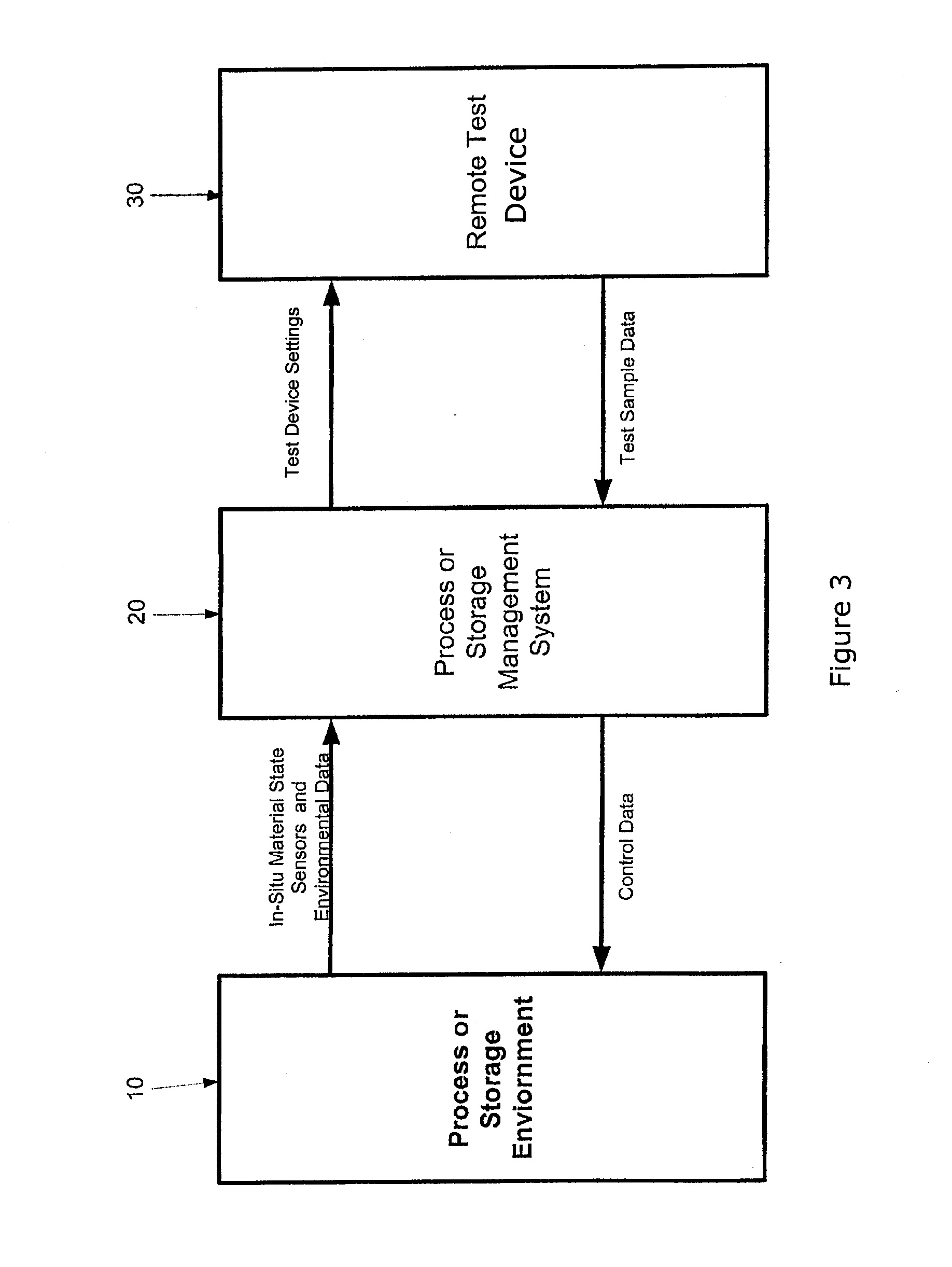
[0121]FIG. 3 generally identifies the Process or Storage Environment 10, the Process or Storage Management System 20, and the Remote Test Device 30 used in this example. Uncured prepreg (carbon fiber fabric impregnated with an epoxy resin) is placed in an autoclave connected to an autoclave data acquisition system. The autoclave is then set in an idle condition waiting for instructions from the process management system 20.

[0122]A separate test sample of the same lot of material used to make the composite material part is placed in an encapsulated sample rheometer test cell 30 compliant with the ASTM D7750-12 test method. The rheometer is placed in a hold state pending instructions from the process management system 20.

[0123]Processing instructions to manage heat transfer and cure state are loaded into the process management system 20, sometimes referred to as the control system 20, and the process is initiated by the operator. The process management system 20 then instructs the aut...

example 2

[0133]The test sample is prepared and processed as in Example 1 except that rheology data obtained from the remote test device 30 is sent to the process or storage management system 20 which initiates a pressurization cycle in the process or storage environment 10 when the test sample exhibits the viscosity appropriate for pressurization.

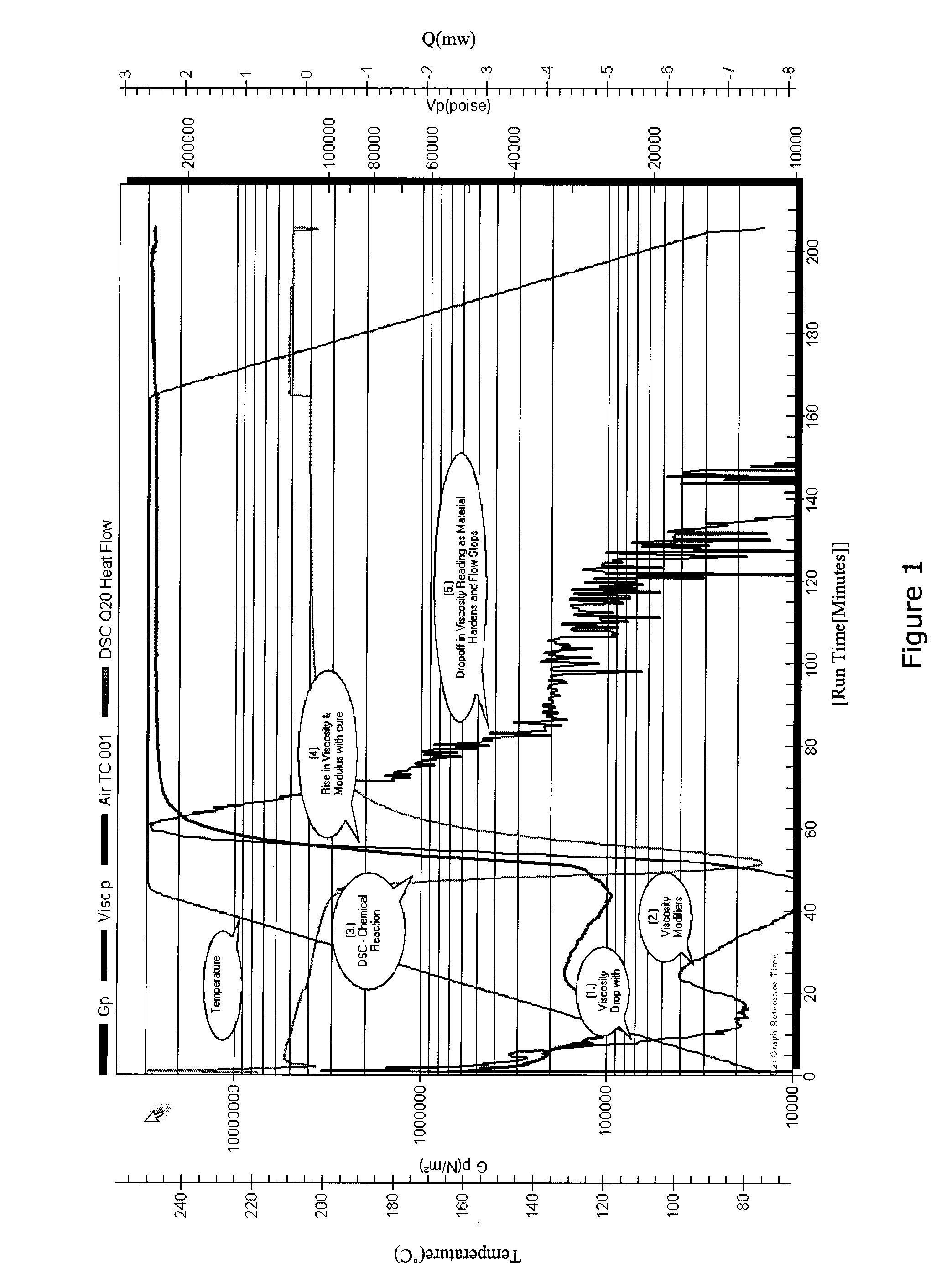
[0134]In one embodiment, the data provided and displayed in the graphs would be used to optimize the process cycle in the process or storage environment 10 by providing information on the state of the test sample. For example, the pressurization to consolidate the composite material part in the process or storage environment 10 is begun as the loss modulus value of the test sample in the remote test device 30 passes 1000. This value is chosen because the resin begins to harden and thus will not further soften and allow the resin to escape the laminate.

example 3

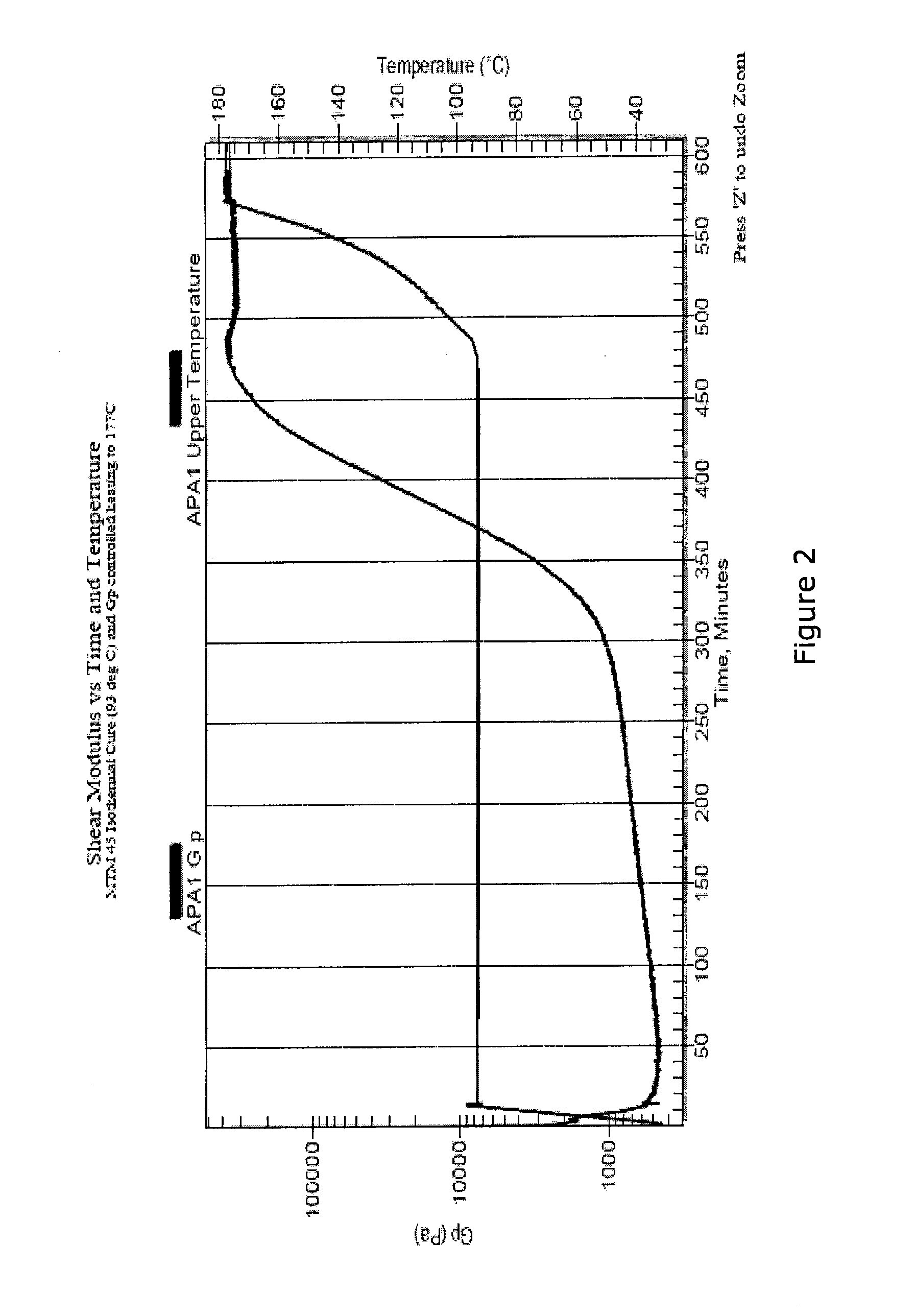
[0135]The process is similar to Example 1 or 2 except the composite material part in the process or storage environment 10 is cured at about 137° C. (see FIG. 5). The elastic modulus of the test sample in the remote test device 30 rises to a steady value after approximately fifty minutes. The standard cure cycle requires the composite material part to remain in the oven (the process or storage environment 10) for an additional three hours or almost a factor of six beyond reaching the glass transition state of the cure temperature (e.g., wherein there is no change in the elastic modulus at that temperature for the duration of the cure cycle). Although other factors may require additional cure time, it is evident that it is possible to determine when the modulus has been achieved for the selected cure temperature and thus when the cure cycle can be terminated. In this case, the cure cycle could have been terminated about three hours earlier than the standard cure instructions dictate,...


PUM

PropertyMeasurementUnit
temperatureaaaaaaaaaa
loss modulusaaaaaaaaaa
glass transition temperatureaaaaaaaaaa

Abstract

A method and system for analyzing and controlling the curing of a composite material part using information derived from composite material test samples obtained using an ex-situ analytical device.

Description

CROSS REFERENCE TO RELATED APPLICATIONS AND INCORPORATION BY REFERENCE STATEMENT[0001]This is a continuation-in-part of U.S. Ser. No. 13 / 603,138, filed Sep. 4, 2012, which is a continuation of U.S. Ser. No. 11 / 732,270, filed Apr. 3, 2007, now abandoned, which was a continuation-in-part of U.S. Ser. No. 10 / 864,161, filed Jun. 9, 2004, now abandoned, which claims the benefit under 35 U.S.C. 119(e) of U.S. Provisional Application Ser. No. 60 / 477,408, filed Jun. 10, 2003, the entirety of which are each hereby expressly incorporated herein by reference.BACKGROUND OF THE PRESENTLY DISCLOSED INVENTIVE CONCEPTS[0002]1. Field of the Presently Disclosed and / or Claimed Inventive Concepts[0003]The presently disclosed inventive concept(s) relates generally to evaluation of material state properties of composite material parts during processing and more particularly but not by way of limitation, to a method and apparatus for implementing management and control of advanced composites based on anal...

Claims


Application Information

Patent Timeline
Patent Type & Authority Applications(United States)
IPC IPC(8): B29C70/54G01N25/20G01N21/65B29C35/02G01N11/00
CPCB29C70/54B29C35/0288B29K2101/12G01N21/65G01N25/20G01N11/00G01N11/14G01N2011/0006G01N2011/002G01N2011/0093B29C35/0227
Inventor ROSE, THOMAS J.ROSE, JOHANN D.
Owner ROCK CREEK RES
Learn More