Electron scanning microscope and image generation method

a technology of electron scanning microscope and electron beam, which is applied in the direction of electrical apparatus, electric discharge tubes, basic electric elements, etc., can solve the problems of liquid specimens, biological/chemical specimens, etc., damaged or changed in state by vacuum, and achieve the effect of reducing the frequency of isolation film replacement, and reducing the probability of isolation film damag

Active Publication Date: 2016-11-24
HITACHI HIGH-TECH CORP
View PDF7 Cites 3 Cited by
  • Summary
  • Abstract
  • Description
  • Claims
  • Application Information

AI Technical Summary

Benefits of technology

[0013]According to the invention, in the scanning electron microscope which enables observation under atmospheric pressure, the contamination attached to the isolation film is decomposed or removed, thus enabling a reduction in th

Problems solved by technology

However, biological/chemical specimens, liquid specimens

Method used


Image

  • Electron scanning microscope and image generation method
  • Electron scanning microscope and image generation method
  • Electron scanning microscope and image generation method

Examples


example 1

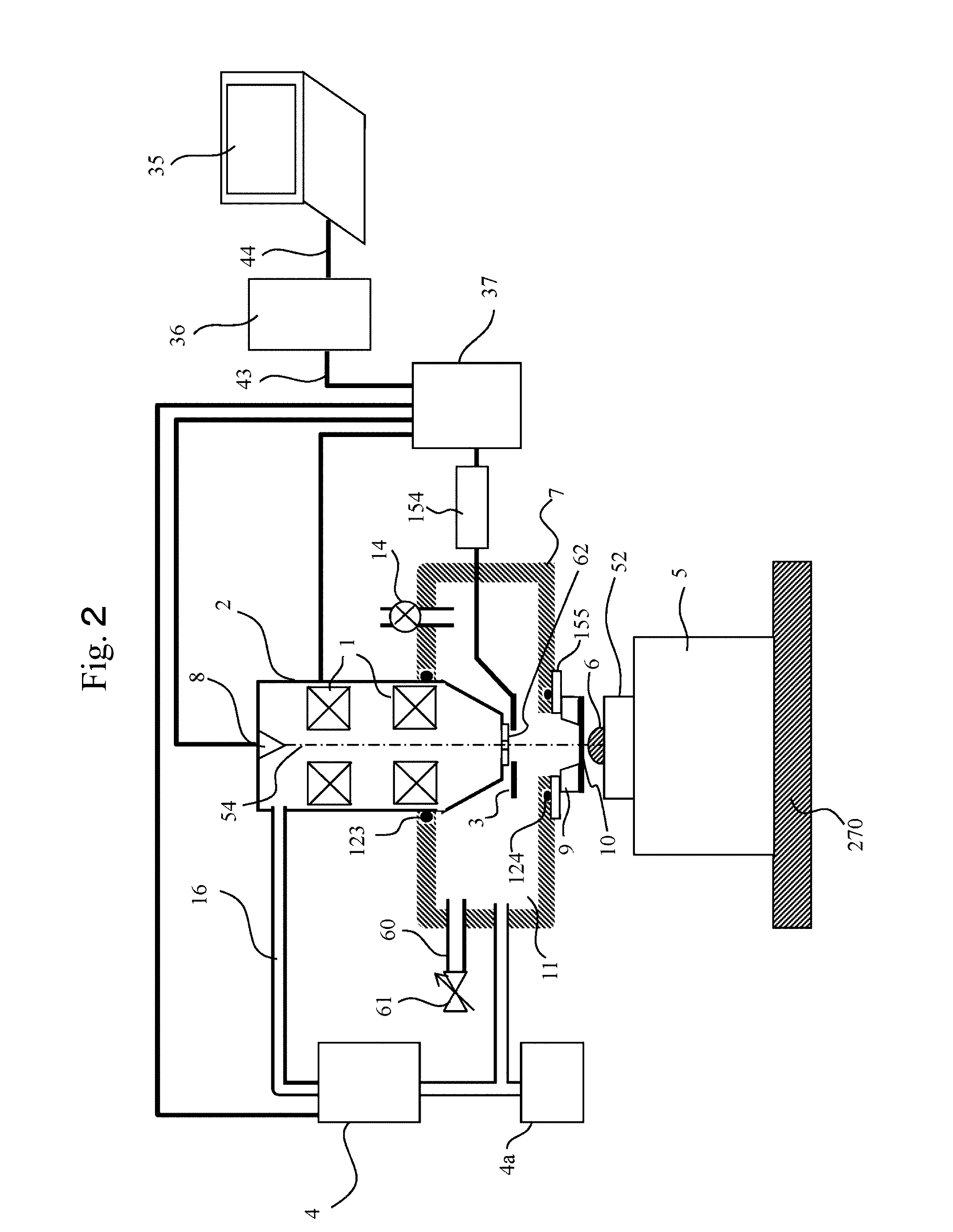
[0029]In this example, a basic embodiment will be described. FIG. 1 shows a view of the overall configuration of the charged particle microscope in this example. While the example below is described on the assumption of a scanning electron microscope, the invention is not limited to this, as described above.

[0030]The charged particle microscope shown in FIG. 1 is mainly made up of an charged particle optical lens barrel 2, a chassis (vacuum chamber) 7 which is connected to and supports the charged particle optical lens barrel 2, a specimen stage 5 arranged in an atmospheric atmosphere, and a control system which controls these. When the charged particle microscope is in use, the insides of the charged particle optical lens barrel 2 and the chassis 7 are vacuum-pumped by a vacuum pump 4. Start and stop operations of the vacuum pump 4 are controlled by the control system as well. Although only one vacuum pump 4 is shown in the illustration, there may be two or more vacuum pumps. It is...

example 2

[0059]Incidentally, in the charged particle beam microscope which enables observation under atmospheric pressure, the observation field of view is limited by the opening area of the isolation film 10. That is, while the isolation film 10 is very thin because of the requirement of transmitting electron beams, the area of the isolation film 10 needs to be very small in order to seal the vacuum with the sufficiently thin isolation film. For example, the area of the isolation film 10 is 250 μm by 250 μm and the area of the isolation film 10 is set to be small enough to endure atmospheric pressure. Thus, observation is performed within the range of the opening area. Therefore, in order to observe a specific place on the specimen 6, the field of view is repeatedly moved to search for the observation target site. This operation is very complicated, significantly impairing the convenience of the charged particle beam microscope which enables observation under atmospheric pressure.

[0060]In t...

example 3

[0072]Hereinafter, an apparatus configuration with which a specimen can be observed easily using a common charged particle beam apparatus will be described. FIG. 6 shows a view of the overall configuration of the charged particle microscope in this example. As in Example 1, the charged particle microscope in this example, too, is made up of the charged particle optical lens barrel 2, the chassis (vacuum chamber) 7 supporting the charged particle optical lens barrel 2 to an apparatus installation surface, the specimen stage 5 and the like. The operations and functions of each of these components, or additional components added to each component are substantially similar to those in Example 1 and therefore the detailed description thereof is omitted.

[0073]The charged particle microscope shown in FIG. 6 has a second chassis (attachment) 121 inserted for use in the chassis 7 (hereinafter the first chassis). The second chassis 121 is made up of a main body part 131 in the shape of a rect...


PUM


Abstract

In a scanning electron microscope, an atmospheric pressure space having a specimen arranged therein and a vacuum space arranged on a charged particle optical system side are isolated from each other using an isolation film that transmits charged particle beams. The scanning electron microscope has an electron optical lens barrel, a chassis, and an isolation film. The electron optical lens barrel radiates a primary electron beam onto a specimen. The chassis is directly bonded to the inside of the electron optical lens barrel and has an inside that turns into a lower vacuum state than the inside of the electron optical lens barrel at least during the radiation of the primary electron beam. The isolation film isolates a space in an atmospheric pressure atmosphere having a specimen mounted therein and the inside of the chassis in a lower vacuum state, and transmits the primary charged particle beam.

Description

TECHNICAL FIELD[0001]The present invention relates to a charged particle beam apparatus which enables observation in the atmosphere or a predetermined gas atmosphere with atmospheric pressure.BACKGROUND ART[0002]In order to observe a very small area on an object, a scanning electron microscope (SEM), transmission electron microscope (TEM) or the like is used. Generally, in these apparatuses, a chassis for arranging a specimen is vacuum-pumped to turn the specimen atmosphere into a vacuum state, and an image of the specimen is picked up. Since electron beams are scattered by gas molecules in the atmosphere or the like, it used to be considered preferable that the passage of electron beams is a vacuum. However, biological / chemical specimens, liquid specimens and the like are damaged or changed in state by a vacuum. Meanwhile, there has been a great need for observation of such specimens with an electron microscope and SEM apparatuses which enable observation of an observation target s...

Claims


Application Information

Patent Timeline
IPC IPC(8): H01J37/18H01J37/28
CPCH01J37/18H01J37/28H01J2237/182H01J2237/2605H01J2237/022H01J2237/164H01J2237/0213H01J37/16
Inventor KAWANISHI, SHINSUKEOOMINAMI, YUUSUKE
Owner HITACHI HIGH-TECH CORP
Why Eureka
Try Eureka