Power amplifier

a power amplifier and amplifier technology, applied in the direction of low-frequency amplifiers, amplifier types, electrical equipment, etc., can solve the problems of low conduction loss, poor channel separation and power supply rejection, and lack of control over the demodulation filter

Active Publication Date: 2016-12-01
BOLECANO HLDG AB
View PDF3 Cites 16 Cited by
  • Summary
  • Abstract
  • Description
  • Claims
  • Application Information

AI Technical Summary

Benefits of technology

[0015]According to a first aspect, a power amplifier is provided comprising an input amplifier, a comparator, a switching circuit, an output filter and a feedback filter. The input amplifier is arranged to receive an input signal of the power amplifier at a positive input of the input amplifier and an output signal of the feedback filter at a negative input of the input amplifier, and the input amplifier is further arranged to have a capacitive feedback from an output of the input amplifier to the negative input of the input amplifier. The comparator is arranged to receive the output signal of the input amplifier at a positive input of the comparator and the output signal of the feedback filter at a negative input of the comparator wherein the comparator provides a control signal on an output of the comparator based on a comparison between signal levels of the signals at the inputs of the comparator. The switching circuit comprises power switches and is arranged to receive the control signal and control the power switches that connect an output of the switching circuit to either a positive supply voltage or a negative supply voltage based on the control signal. The output filter is arranged to receive an output signal provided at the output of the switching circuit and provide a filtered signal thereof to an output of the power amplifier. The feedback filter is arranged to receive the output of the power amplifier and provide a filtered feedback signal to the negative input of the comparator and towards the negative input of the input amplifier.

Problems solved by technology

The only losses that appear are the low conduction losses during the “on” state and the switching losses from each time the output stage changes state.
A disadvantage with this reference signal technique is that the average value of the pulse train only corresponds to the set value as long as the supply voltages are constant and the state shift is infinitely fast plus of course, the triangle wave has to be ideal.
The reference signal technique does not have any feedback resulting in an absence of control over the demodulation filter.
The channel separation and power supply rejection become very poor.
A DSP solution also is more complicated and expensive.
A comparator is used to compare the average of the pulse train to the set value giving an error as a result.
Without additional circuitry the switching frequency would be equal to the filter resonance frequency which usually is around 50 kHz and this normally is not acceptable.
The result of this post-filter self-oscillating topology is therefore that the linear distortion, i.e. distortion which does not add new frequency content like amplitude and phase, is low for being a class D amplifier but the non-linear distortion is still relatively high compared to a high quality amplifier.
However, in a pre-filter self-oscillating topology the linear distortion becomes high, i.e. the frequency response and phase is totally load dependant and a desired response curve can only be obtained with specific load impedance.

Method used


Image

  • Power amplifier
  • Power amplifier
  • Power amplifier

Examples


Embodiment Construction

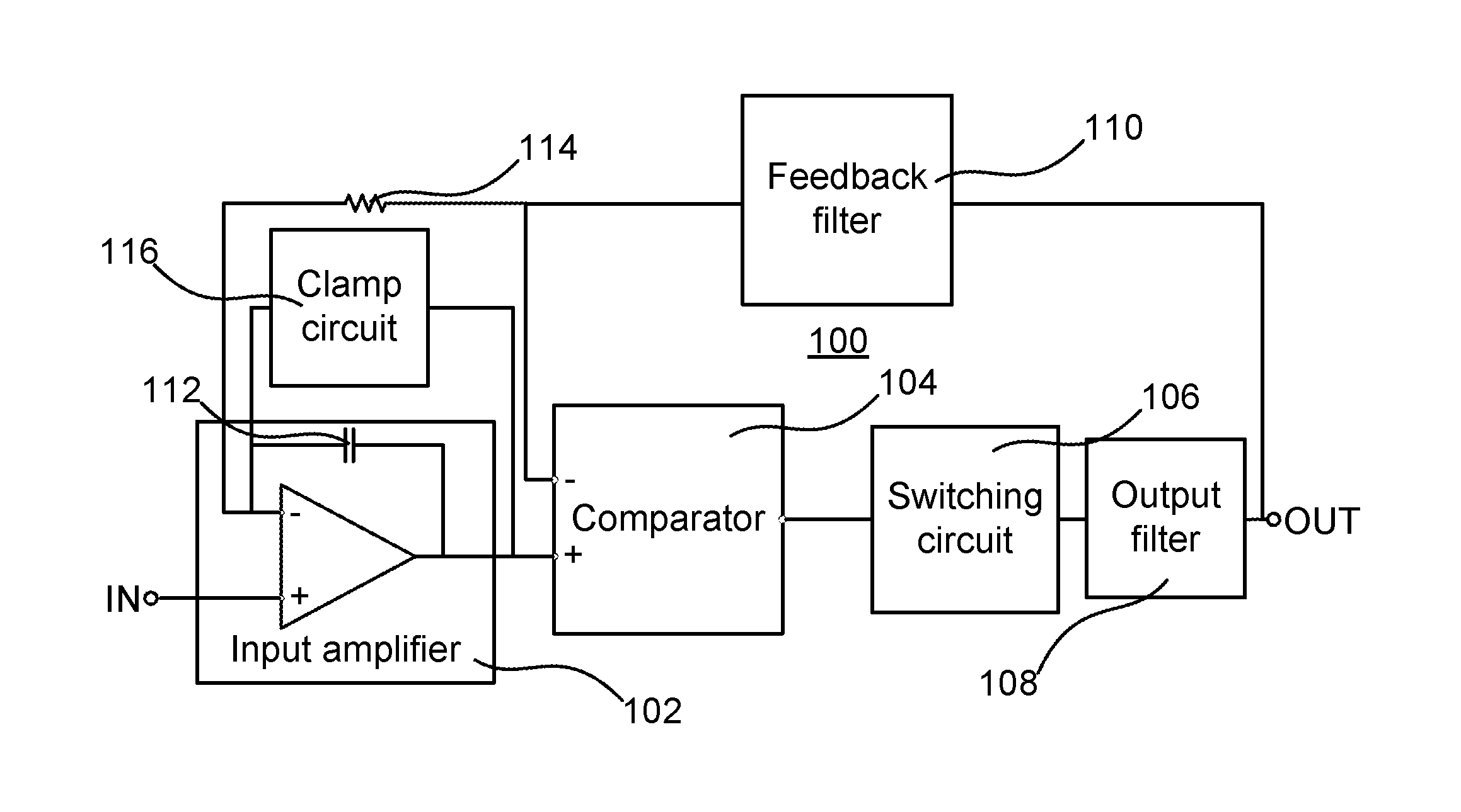
[0038]The disclosure below relates to a power amplifier for amplifying an electric input signal in an operational frequency range, e.g. audio frequency range, and providing an output signal. The principle of the power amplifier comprises switching means for generating a square wave signal by alternately switching the square wave signal to a first supply voltage or a second supply voltage, and filter means for generating a power output signal by low pass filtering the square wave signal. The power amplifier further comprises input means for receiving the electric signal and driving the switching means, and a local feedback circuit connecting the output signal towards an input of the switching means, as will be further elucidated below.

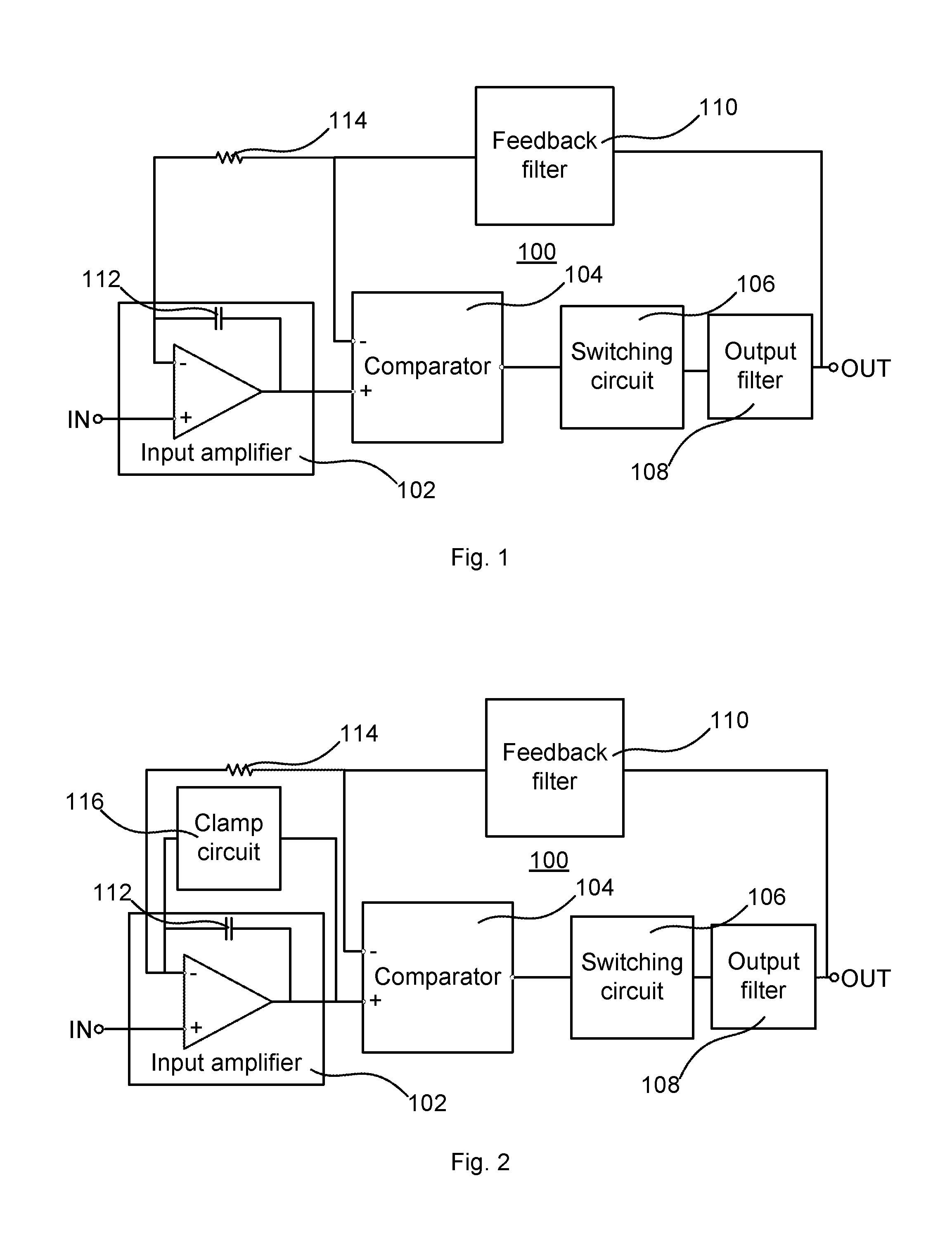
[0039]FIG. 1 schematically illustrates a power amplifier 100 according to an embodiment. The power amplifier 100 comprises an input amplifier 102, a comparator 104, a switching circuit 106, an output filter 108 and a feedback filter 110. The respective ...


PUM


Abstract

A power amplifier includes an input amplifier, a comparator, a switching circuit, an output filter and a feedback filter. The input amplifier receives an input signal of the power amplifier at a positive input of the input amplifier and an output signal of the feedback filter at a negative input of the input amplifier. The input amplifier has a capacitive feedback from an output of the input amplifier to the negative input of the input amplifier. The comparator receives the output signal of the input amplifier at a positive input of the comparator and the output signal of the feedback filter at a negative input of the comparator. The comparator provides a control signal based on a comparison between signal levels of the signals at the positive and the negative inputs of the comparator. The switching circuit includes power switches and receives the control signal and controls the power switches that connect an output of the switching circuit to either a positive supply voltage or a negative supply voltage based on the control signal. The output filter receives an output signal provided at the output of the switching circuit and provides a filtered signal thereof to an output of the power amplifier. The feedback filter receives the output of the power amplifier and provides a filtered feedback signal to the negative input of the comparator and towards the negative input of the input amplifier.

Description

PRIORITY STATEMENT[0001]This US non-provisional application claims priority under 35 USC §119 to Swedish Patent Application No. 1550677-7, which was filed on May 26, 2015, the entire content of which is incorporated herein by reference.BACKGROUND1. Technical Field[0002]The present invention generally relates to a power amplifier, and in particular to a self-oscillating class D power amplifier.2. Description of Related Art[0003]Switching power amplifiers also referred to as pulse modulation amplifiers, pulse width modulation (PWM) amplifiers or class D amplifiers are commonly used in applications where power dissipation is an important factor. Class D amplifiers have the benefit of lowering power consumption and decreasing the size / weight in view of e.g. class A amplifiers and hence the use of raw materials.[0004]In such amplifiers there is an input stage for receiving an electrical input signal to be amplified, a modulating / switching or power stage and a filter. The switching stage ...

Claims


Application Information

Patent Timeline
Patent Type & Authority Applications(United States)
IPC IPC(8): H03F3/217H03F3/45H03F3/183
CPCH03F3/217H03F3/183H03F2200/66H03F2200/171H03F2200/78H03F3/45475H03F1/34H03F3/187H03F2200/03
Inventor BOSTROM, PATRIK
Owner BOLECANO HLDG AB
Why Eureka
Try Eureka