
Front-End Module for Carrier Aggregation Mode

a carrier aggregation and module technology, applied in the direction of transmission, electrical equipment, etc., can solve the problems of power loss, higher insertion loss, power loss, etc., and achieve the effect of enhancing gate width, enhancing gate width, and increasing linearity of switch

Active Publication Date: 2016-12-15
SNAPTRACK
View PDF2 Cites 16 Cited by
  • Summary
  • Abstract
  • Description
  • Claims
  • Application Information

AI Technical Summary

Benefits of technology

The invention is about a front-end module that can be used in both single band mode and carrier aggregation mode. It is flexible and expandable, which helps it attain better performance compared to existing front-end modules. This is achieved by using a cascade of two switches, which avoids high loss and poor isolation. Overall, the front-end module provides a more cost-effective and efficient solution for combining signal paths and improving performance.

Problems solved by technology

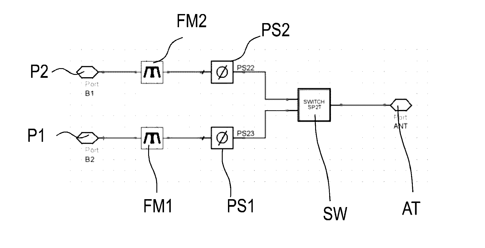
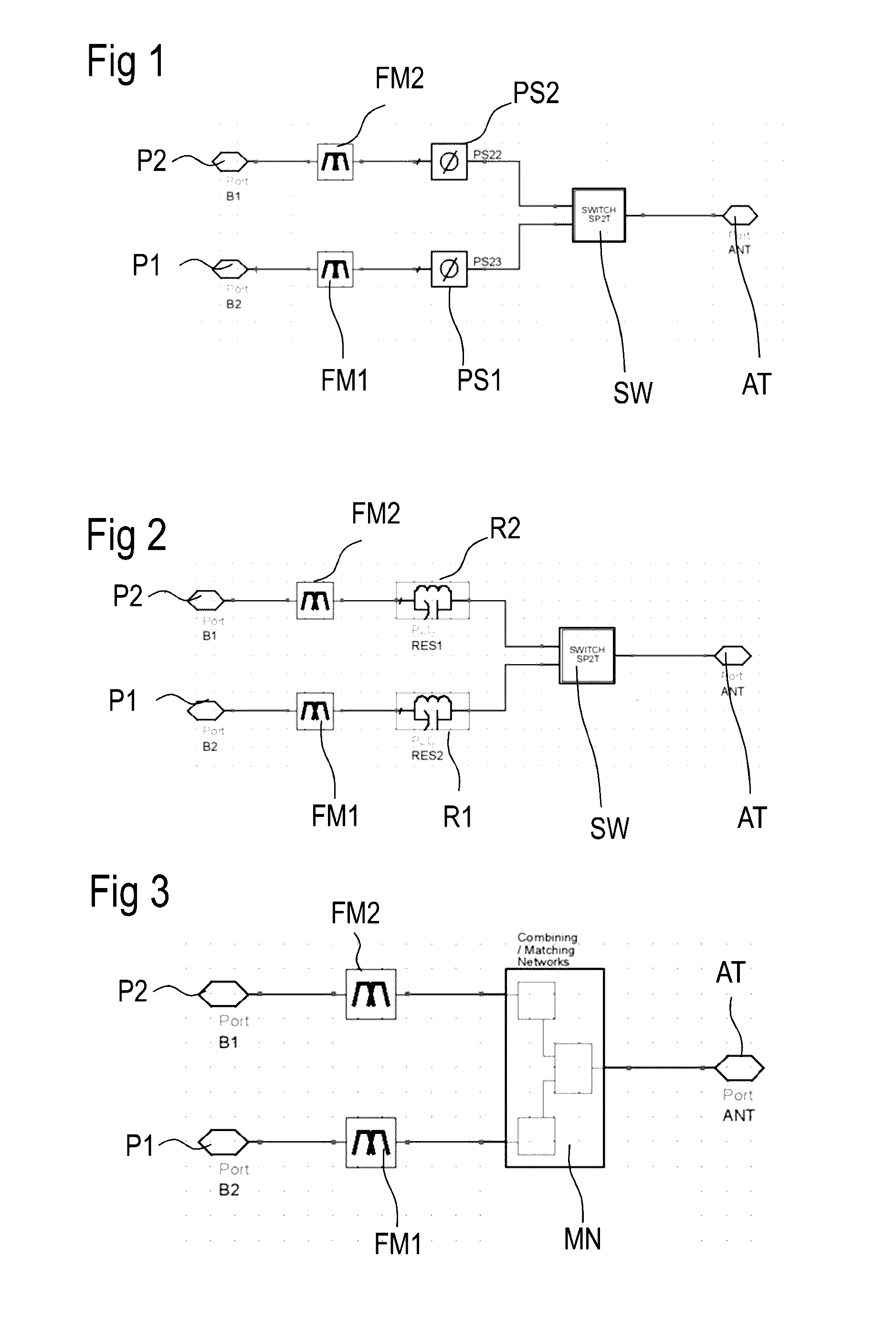
In receive (RX) CA mode, with signals going from one antenna (AT) to receiver via low noise amplifiers (LNAs), it is important that the signal paths do mutually block and not load each other for each combination of pass band frequency and counter band frequency, because that would otherwise result in power loss and higher insertion loss.
In transmit (TX) CA mode, with signals going from transmitting power amplifiers (PAs) represented by ports P1 and P2, it is important that the signal paths do mutually block and not load each other for each combination of pass band frequency and counter band frequency, because that would otherwise result in power loss and lower output power and lower efficiency.
Front-end modules that can operate within a majority of these bands and band combinations and that are designed according to the conventional approach become big and complex with adverse effects on their performance.
Such complex front ends show high insertion losses (IL), and reduced isolation.
Further, costs and effort for development increase and the chances for a successful business with these developments get worse.
As a consequence, the insertion loss in single band operation mode increases due to the loss of the phase shifter.
This is because L and C components that are used have a limited quality factor Q. And in carrier aggregation mode, the insertion loss increases also due to the loading of the counter band in parallel.
That is because the magnitude of the OOB reflection coefficient F of the counter band—at the combining reference plane, at the switch—is not an ideal open but finite due to the limited Γ (reflection coefficient) of the filter and the limited Q (quality factor) of the phase shifter.
Another disadvantage is that this solution is more or less limited to two parallel bands.
This solution is practically also limited to a parallel circuit of only two signal paths operating in two different bands.
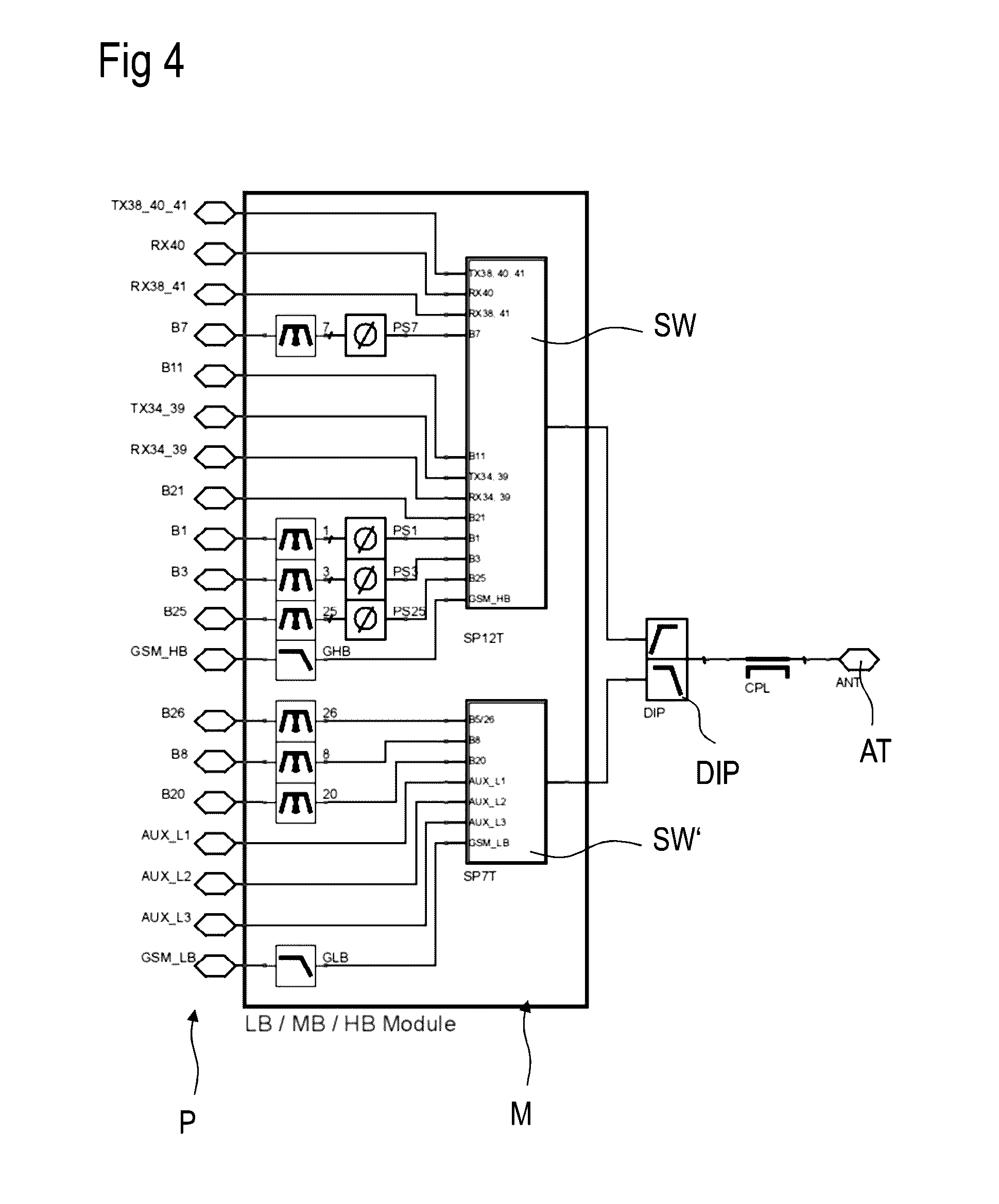
A front-end module like that depicted in FIG. 4 gives rise to different problems.
Furthermore, the linearity of the switch gets worse for high throw count.
Second, with all bands circuited in parallel via the switch, it becomes more difficult to address all different carrier aggregation band combinations with phase shifters.
The design becomes complex or nearly impossible, will be big in size and provides too high insertion losses.
Third, with so many bands and carrier aggregation band combinations, it is not attractive for the business of a manufacturer to integrate all the bands and band combinations in one module.

Method used


Image

  • Front-End Module for Carrier Aggregation Mode
  • Front-End Module for Carrier Aggregation Mode
  • Front-End Module for Carrier Aggregation Mode

Examples


first embodiment

[0068]FIG. 5 shows a first embodiment according to the invention. In principle, the new front-end module is a cascade of a first switch SW1 and a second switch SW2. First and second switch are connected by at least three different signal paths. One of the connecting paths is a bypass BP without phase shifter and without resonator, directly connecting first and second switches. At least one notch path N1, NP2 connects another output OP1 of the first switch SW1 with the input of the second switch SW2. The notch path NP comprises a notch and the notch comprises a resonator R1. The further notch path NP2 and others are connecting further outputs of the first switch SW1 with the input of the second switch SW2 with further notches arranged therein. The notches are tuned to provide a high impedance state for frequencies within the counter band of a carrier aggregation mode.

[0069]In the paths, matching may be needed to stay at a certain impedance level or to match components before connecti...

third embodiment

[0108]A third embodiment according to c) of FIG. 9 shows a shunt series resonance circuit of a capacitor C and an inductance LP. Within the signal line, a transmission line TL is inserted. The shunt is coupled to the series line via a switch to toggle between single mode operation and CA mode operation.

[0109]Further circuits known from the art having a different circuit topology but realizing a series open circuit for the frequencies to be blocked are possible, too. By default, the resonators are tuned at the OOB frequencies, thus providing an open.

[0110]Tuning of the resonators, phase shifters, etc. may be done by further using the parasitics of components present in the module or by parasitics that are inherent to conductor lines. So, an inductor already has a certain parasitic shunt capacitance and a capacitor already has small parasitic series inductance. These parasitics have to be taken into account when designing a resonator, phase shifter, or another circuit using LC element...


PUM


Abstract

A new front-end module is disclosed. In an embodiment the front-end module is configured to operate carrier aggregation modes using a cascade of switches and an intelligent set of bands. The module can be assembled by sub-modules.

Description

[0001]This patent application is a national phase filing under section 371 of PCT / EP2014 / 055114, filed Mar. 14, 2014, which is incorporated herein by reference in its entirety.BACKGROUND[0002]In a cellular communication with carrier aggregation (CA) enabled, multiple bands are active at the same time (single mode pass band plus CA mode counter band). In such a carrier aggregation mode, two or more signal paths containing filters or duplexers are circuited in parallel to increase the data rate. No problems arise if in the carrier aggregation mode each band uses a separate antenna. However, in case the two signal paths assigned to two aggregated bands are coupled in parallel to the same antenna mutual loading or blocking is required to avoid power loss.[0003]In receive (RX) CA mode, with signals going from one antenna (AT) to receiver via low noise amplifiers (LNAs), it is important that the signal paths do mutually block and not load each other for each combination of pass band frequ...

Claims


Application Information

Patent Timeline
Patent Type & Authority Applications(United States)
IPC IPC(8): H04B1/00
CPCH04B1/006H04B1/0053
Inventor BALM, BARTDESTOUCHES, CAREMVAN DEN OEVER, LEON C.M.REMCO, OOIJMAN
Owner SNAPTRACK
Learn More