Method of forming a building panel or surface element and such a building panel and surface element

Active Publication Date: 2016-12-22
VÄLINGE INNOVATION AB
View PDF6 Cites 63 Cited by
  • Summary
  • Abstract
  • Description
  • Claims
  • Application Information

AI Technical Summary

Benefits of technology

[0081]The mesh structure may also increase, or decrease, the heat conductivity of the building panel.
[0082]Furthermore, the mesh

Problems solved by technology

In the past it was more difficult to create advanced multi colour designs such as for example wood decors.
Lamination of impregnated textile materials and papers is a difficult and costly production method.
Thereby, a material such as a textile, which otherwise would not provide sufficient wear resistance, may form the surface of the building panel or surface element or surface element, and the decorative properties of such materials can be used for a building panel or surface element subjected to wear.
Furthermore, the sub-layer may also provide water-resistance to a material, which

Method used


Image

  • Method of forming a building panel or surface element and such a building panel and surface element
  • Method of forming a building panel or surface element and such a building panel and surface element
  • Method of forming a building panel or surface element and such a building panel and surface element

Examples


example 1

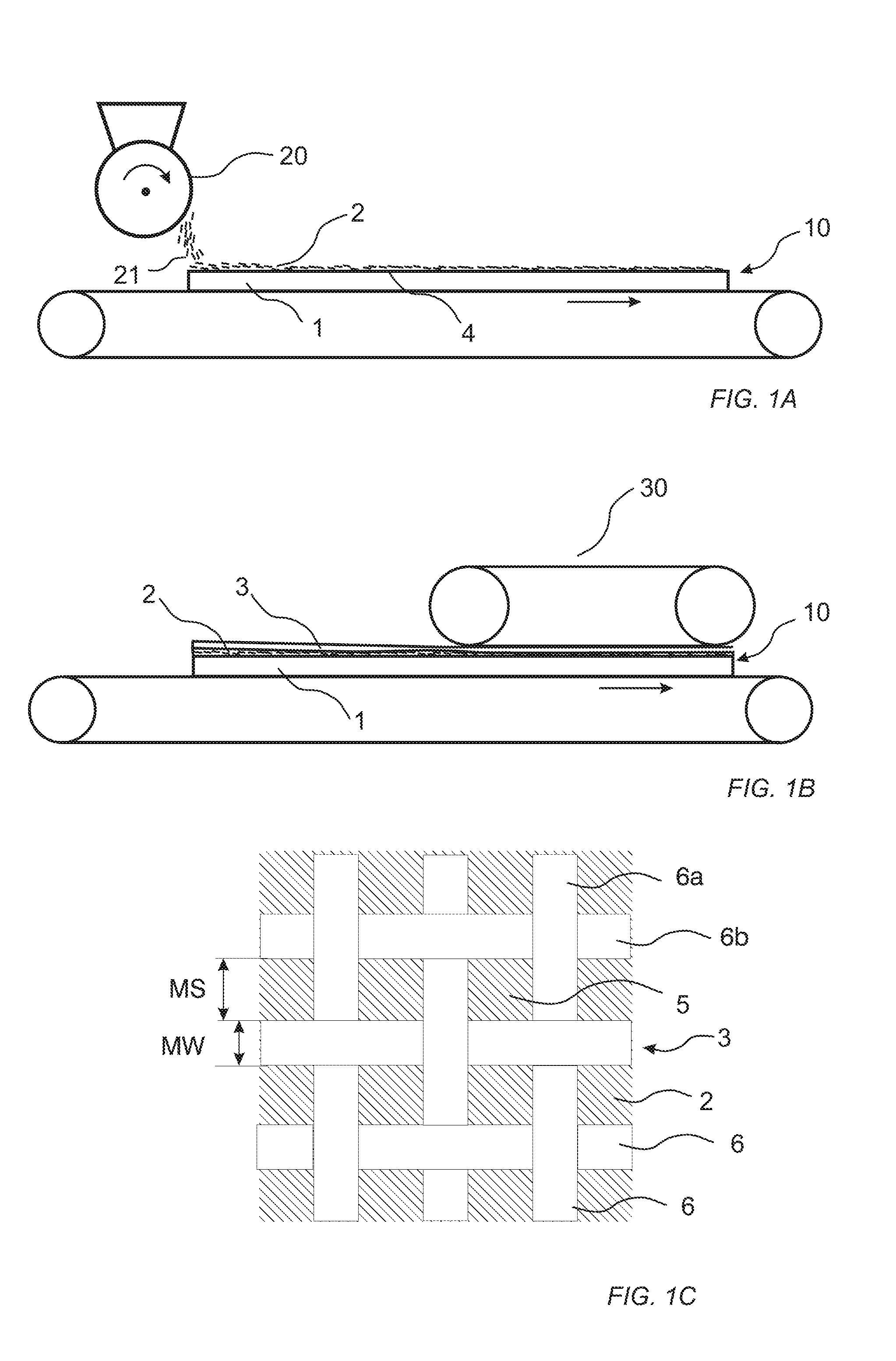
[0220]625 g / m2 of a powder mixture, comprising 30.41 wt % wood fibres, 8.8 wt % aluminium oxide (Alodur ZWSK 180-ST), 52.5 wt % melamine formaldehyde resin (Kauramin 773) and 8.29 wt % of pigments was scattered on a 10.0 mm HDF board for forming a sub-layer. A textile fabric was positioned on the sub-layer prior to pressing the assembly in a short cycle press for 35 seconds at 40 kg / cm2 with a press plate temperature of 140° C. During pressing, the sub-layer has permeated through the fabric. The resulting product was a building panel with a surface layer of textile being impregnated by the sub-layer during pressing.

example 2

[0221]600 g / m2 of a powder mixture, comprising 33 wt % wood fibres, 10 wt % aluminium oxide (Alodur ZWSK 180-ST), 47 wt % melamine formaldehyde resin (Kauramin 773) and 10 wt % BaSo4 (BB 30 EX) was scattered on a 10.0 mm HDF board for forming a sub-layer. A denim fabric was applied on the sub-layer. An overlay comprising a resin impregnated paper (Liquilay, AC3-N) was applied on the denim fabric. Two backing papers of 140 g / m2 each were applied to the rear side of the HDF board. The assembly was pressed in a short cycle press during 50 seconds at 40 bar with a press plate temperature of 160° C. During the pressing, the sub-layer has permeated through the fabric. The resulting product was a building panel with a surface layer of a denim fabric being impregnated by the sub-layer during pressing.

example 3

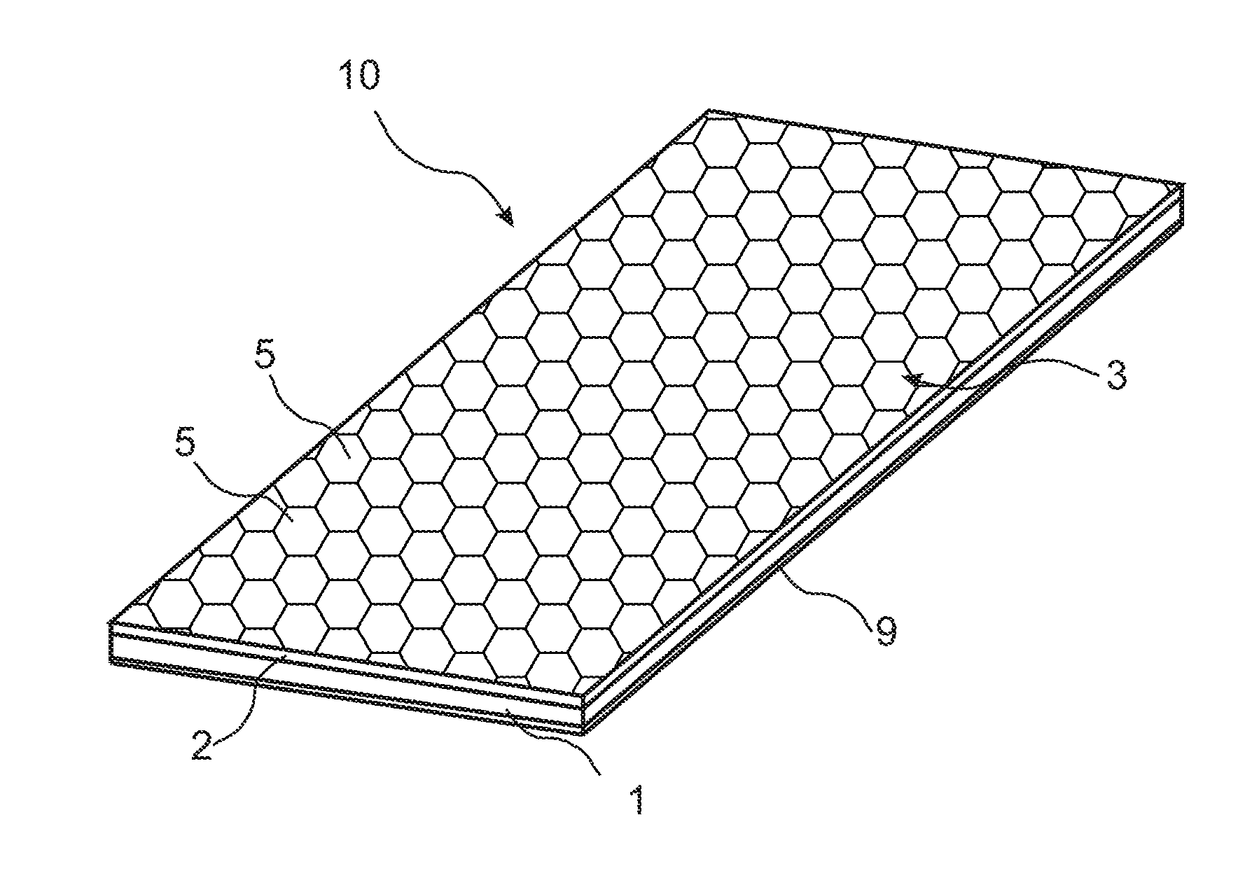
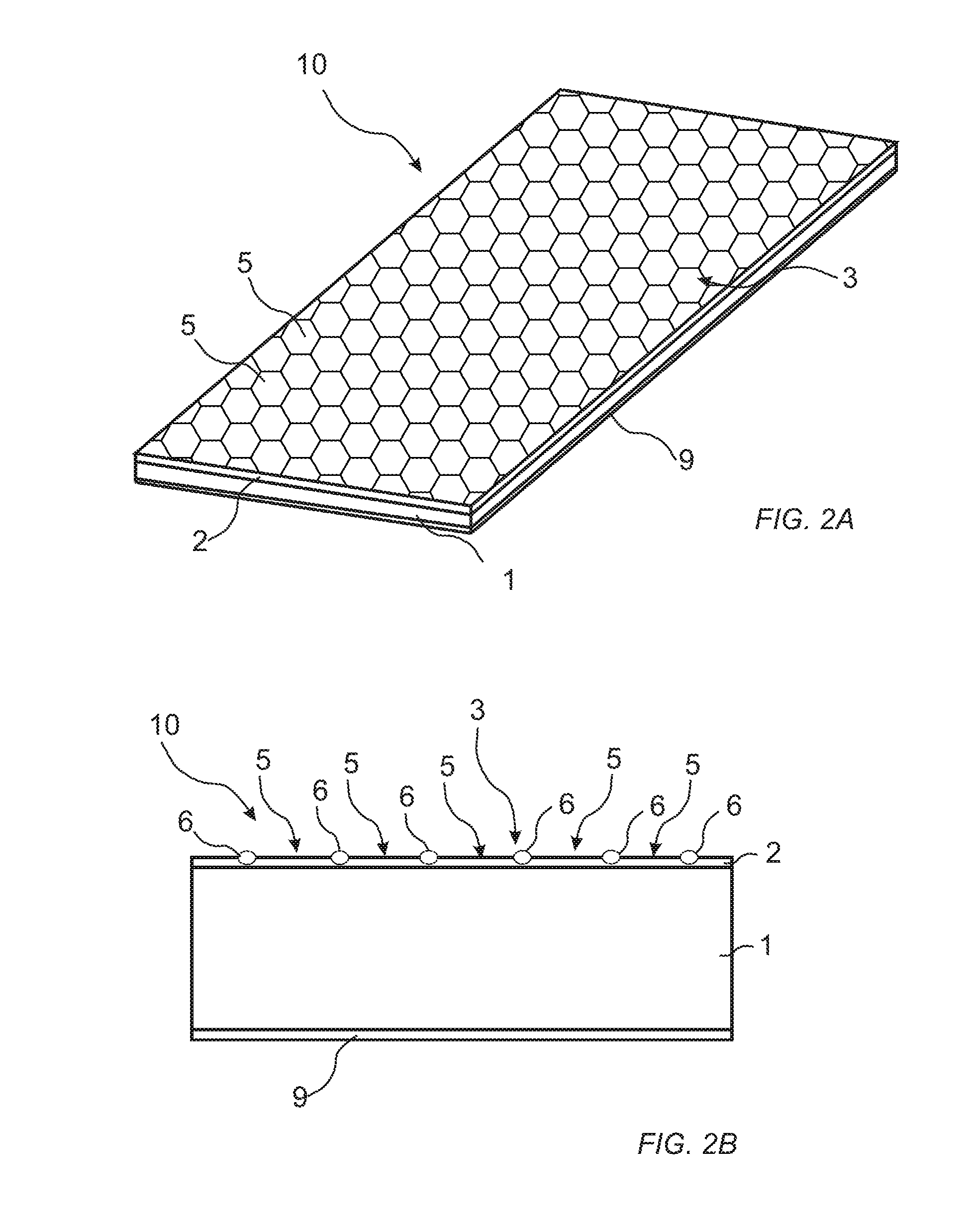
[0222]625 g / m2 of a powder mixture, comprising 30.41 wt % wood fibres, 8.8 wt % aluminium oxide (Alodur ZWSK 180-ST), 52.5 wt % melamine formaldehyde resin (Kauramin 773) and 8.29 wt % of pigments was scattered on a 10.0 mm HDF board for forming a sub-layer. An expanded metal sheet of aluminium, having an aperture dimension long way of 5.9 mm, an aperture dimension short way of 3.4 mm and a width of 0.8 mm was positioned on the sub-layer prior to pressing the assembly in a short cycle press for 35 seconds at 40 kg / cm2 with a press plate temperature of 140° C. During pressing, the sub-layer has at least partly filled the meshes of the expanded metal sheet. The resulting product was a building panel with a surface layer of expanded metal being at least partly encapsulated by the sub-layer after pressing.


PUM

PropertyMeasurementUnit
Temperatureaaaaaaaaaa
Widthaaaaaaaaaa
Pressureaaaaaaaaaa

Abstract

A method of forming a building panel or a surface element, including providing a substrate, applying a sub-layer on the substrate, applying a mesh structure on the sub-layer, and applying heat and pressure to the mesh structure such that the sub-layer at least partially fills meshes of the mesh structure. Also, to such a building panel and a surface element.

Description

CROSS REFERENCE TO RELATED APPLICATIONS[0001]The present application claims the benefit of Swedish Application No. 1550827-8, filed on Jun. 16, 2015. The entire contents of Swedish Application No. 1550827-8 are hereby incorporated herein by reference in their entirety.TECHNICAL FIELD[0002]The present disclosure relates to a method of forming a building panel or a surface element comprising a mesh structure, and such a building panel and surface element.TECHNICAL BACKGROUND[0003]A new type of floors has recently been developed with a solid surface comprising a substantially homogenous mix of wood particles, a binder and wear resistant particles. Such floor and building panels are marketed under the trademark NADURA®.[0004]The panels are produced according to a production method, which is described in WO 2009 / 065769, wherein the mix comprising wood fibres, binder and wear resistant particles is applied in powder form on a core. Lignocellulosic wood material may be used. The wood fibre...

Claims


Application Information

Patent Timeline
IPC IPC(8): E04C2/26B32B5/02B32B21/04E04C2/10B32B37/06
CPCE04C2/26E04C2/10B32B37/06B32B21/04B32B2307/724B32B2260/026B32B2311/00B32B2375/00B32B2305/38B32B5/02B32B33/00B32B37/10B32B37/1027B32B37/24B32B38/08B32B2307/554B32B2419/04B32B5/028B32B13/02B32B13/06B32B13/12B32B13/14B32B15/02B32B15/08B32B27/06B32B27/12B32B27/20B32B2260/021B32B2260/046B32B2262/02B32B2262/062B32B2262/067B32B2307/538B32B2607/00E04F15/102E04F15/107
Inventor PERVAN, DARKOWING RDH, PETERZIEGLER, GORANMEIJER, THOMAS
Owner VÄLINGE INNOVATION AB
Why Eureka
Try Eureka