Power generation system exhaust cooling

Active Publication Date: 2016-12-29
GENERAL ELECTRIC CO
View PDF17 Cites 17 Cited by
  • Summary
  • Abstract
  • Description
  • Claims
  • Application Information

AI Technical Summary

Benefits of technology

[0007]A first aspect of the disclosure provides an airflow control system for a combined cycle turbomachine system, including: an airflow generation system for attachment to a rotatable shaft of a gas turbine system, the airflow generation system drawing in an excess flow of air through an air intake section; a mixing area for receiving an exhaust gas stream produced by the gas turbine system; an air extraction system for extracting a first portion of the excess flow of air to provide bypass air, and for diverting the bypass air into the mixing area to reduce a temperature of the exhaust gas stream; and an airflow regulation system for diverting a second portion of the excess flow of air into the compressor component and, in response to an under-frequency grid event, for increasing the second portion of the excess flow of air diverted into the compressor component.
[0008]A second aspect of the disclosure provides a turbomachine system, including:

Problems solved by technology

Further, operating gas turbines at lower loads for a considerable amount of time reduces the power provided to the power grid during the crucial start-up period.
Large increases in the electrical power demand placed upon an electrical power distribution grid will tend to reduce the electrical operational frequency of the grid, c

Method used


Image

  • Power generation system exhaust cooling
  • Power generation system exhaust cooling
  • Power generation system exhaust cooling

Examples


Example

[0020]It is noted that the drawing of the disclosure is not to scale. The drawing is intended to depict only typical aspects of the disclosure, and therefore should not be considered as limiting the scope of the disclosure. In the drawing, like numbering represents like elements between the drawings.

DETAILED DESCRIPTION OF THE INVENTION

[0021]As indicated above, the disclosure relates generally to power generation systems, and more particularly, to systems and methods for cooling the exhaust gas of power generation systems.

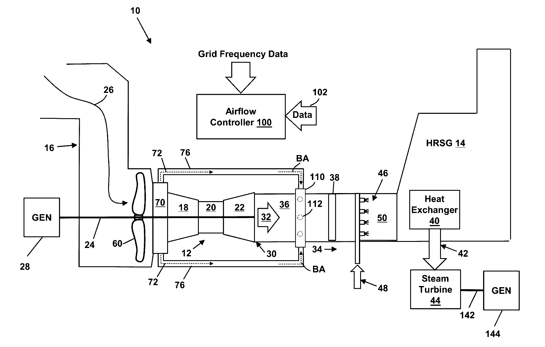
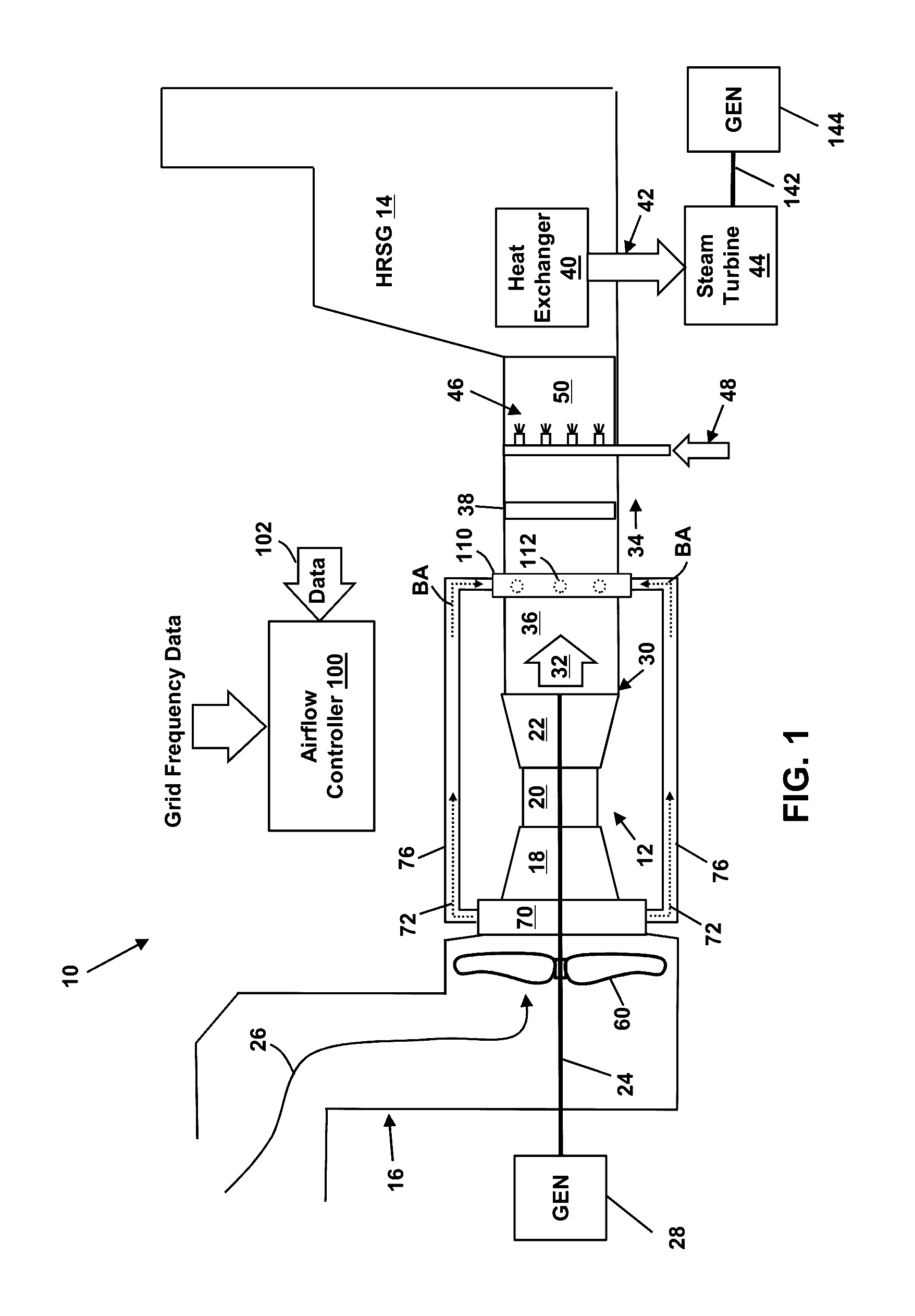
[0022]FIGS. 1 and 3 depict block diagrams of turbomachine systems (e.g., combined cycle (CC) power generation systems 10). According to embodiments, the CC power generation systems 10 each include a gas turbine system 12 and a heat recovery steam generator (HRSG system 14). The gas turbine system 12 may combust liquid or gas fuel, such as natural gas and / or a hydrogen-rich synthetic gas, to generate hot combustion gases to drive the gas turbine system 12.
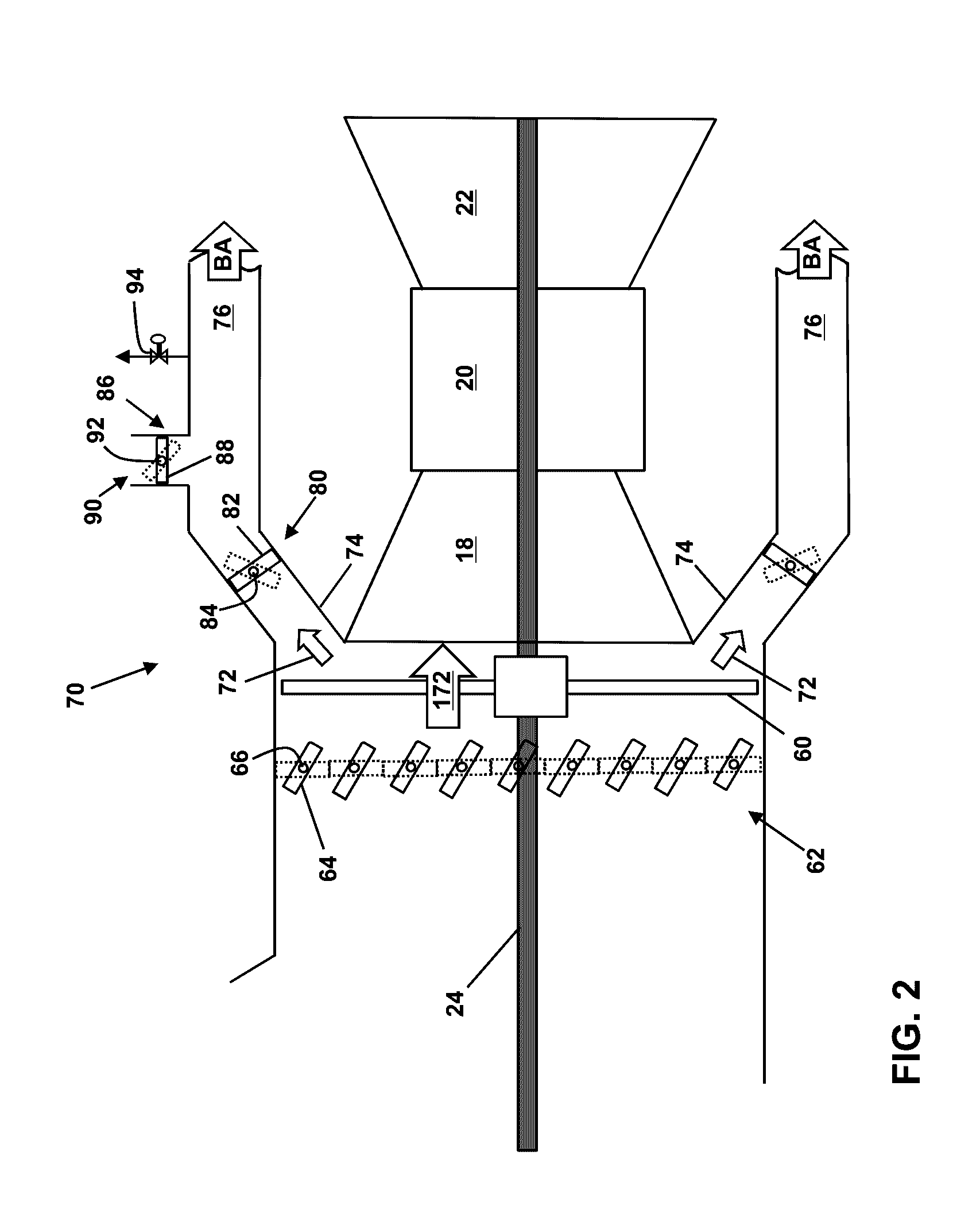
[0023]The ...


PUM


Abstract

An airflow control system for a combined cycle turbomachine system in accordance with an embodiment includes: an airflow generation system for attachment to a rotatable shaft of a gas turbine system, the airflow generation system drawing in an excess flow of air through an air intake section; a mixing area for receiving an exhaust gas stream produced by the gas turbine system; an air extraction system for extracting a first portion of the excess flow of air to provide bypass air, and for diverting the bypass air into the mixing area to reduce a temperature of the exhaust gas stream; and an airflow regulation system for diverting a second portion of the excess flow of air into the compressor component and, in response to an under-frequency grid event, for increasing the second portion of the excess flow of air diverted into the compressor component.

Description

CROSS-REFERENCE TO RELATED APPLICATIONS[0001]This application is related to co-pending US application Ser. No. ______, GE docket numbers 280650-1, 280685-1, 280687-1, 280688-1, 280692-1, 280707-1, 280714-1, 280730-1, 280731-1, 280815-1, 281005-1, 281004-1, and 281003-1 all filed on ______.BACKGROUND OF THE INVENTION[0002]The disclosure relates generally to power generation systems, and more particularly, to systems and methods for cooling the exhaust gas of power generation systems.[0003]Utility power producers use combined cycle (CC) power generation systems because of their inherent high efficiencies and installed cost advantage. CC power generation systems typically include a gas turbine, a heat recovery steam generator (HRSG), and a steam turbine. The heat recovery steam generator uses the hot exhaust gas from the gas turbine to create steam, which drives the steam turbine. The combination of a gas turbine and a steam turbine achieves greater efficiency than would be possible in...

Claims


Application Information

Patent Timeline
IPC IPC(8): F01N3/05F01N3/20F02C7/141F02C3/30
CPCF01N3/05F02C3/30F01N3/2066F05D2220/31F05D2260/2322F05D2220/36F02C7/141F02C6/08F02C6/18F05D2220/72F05D2260/606Y02E20/16Y02E20/14
Inventor REED, ROBERT JOSEPHDAVIS, JR., LEWIS BERKLEYKULKARNI, PARAG PRAKASH
Owner GENERAL ELECTRIC CO
Why Eureka
Try Eureka