Heat transfer device

Active Publication Date: 2017-01-05
DENSO CORP
View PDF6 Cites 11 Cited by
  • Summary
  • Abstract
  • Description
  • Claims
  • Application Information

AI Technical Summary

Benefits of technology

[0018]According to the present disclosure, the composite member includes the heat generation side composite member disposed on one side of the heat conductor, and the heat radiation side composite member disposed on the other side of the heat conductor. Hence, one end of the heat conductor is embedded into the heat generation side composite member. In addition, the other end of the heat conductor is embedded into the heat radiation side composite member. Since the embedded heat conductor is crosslinked with the carbon fibers in the respective composite members through the carbon nanotubes, the heat can be efficiently transferred between one composite member and the other composite member.
[0019]The fixing member constituting a connector may be coupled with the

Problems solved by technology

In the configuration disclosed in Patent Document 1, the circuit board and the heat sink are adjacent to each other and integrated together, and there is a limit to the mountability and the assembly of those components in a vehicle.
Therefore, such a configuration may not be preferable for cooling of the electronic devices dispersed inside of the vehicle.
In other words, even if heat generated in semiconductor can be efficiently transferred to the heat sink, the electronic devices have to be cooled by air cooling of the heat sink, individually, and there is a limit to the cooling of the semiconductor associated with a cooling perf

Method used


Image

  • Heat transfer device
  • Heat transfer device
  • Heat transfer device

Examples


first embodiment

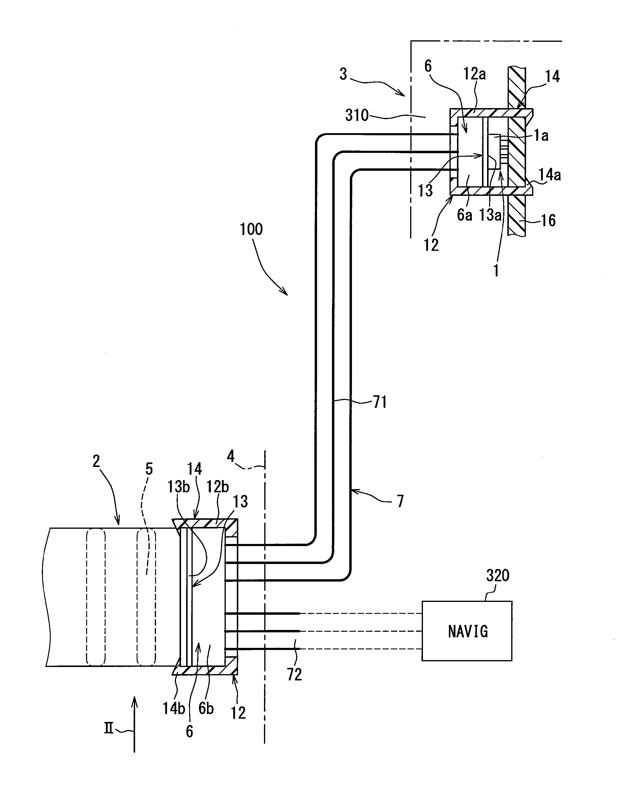
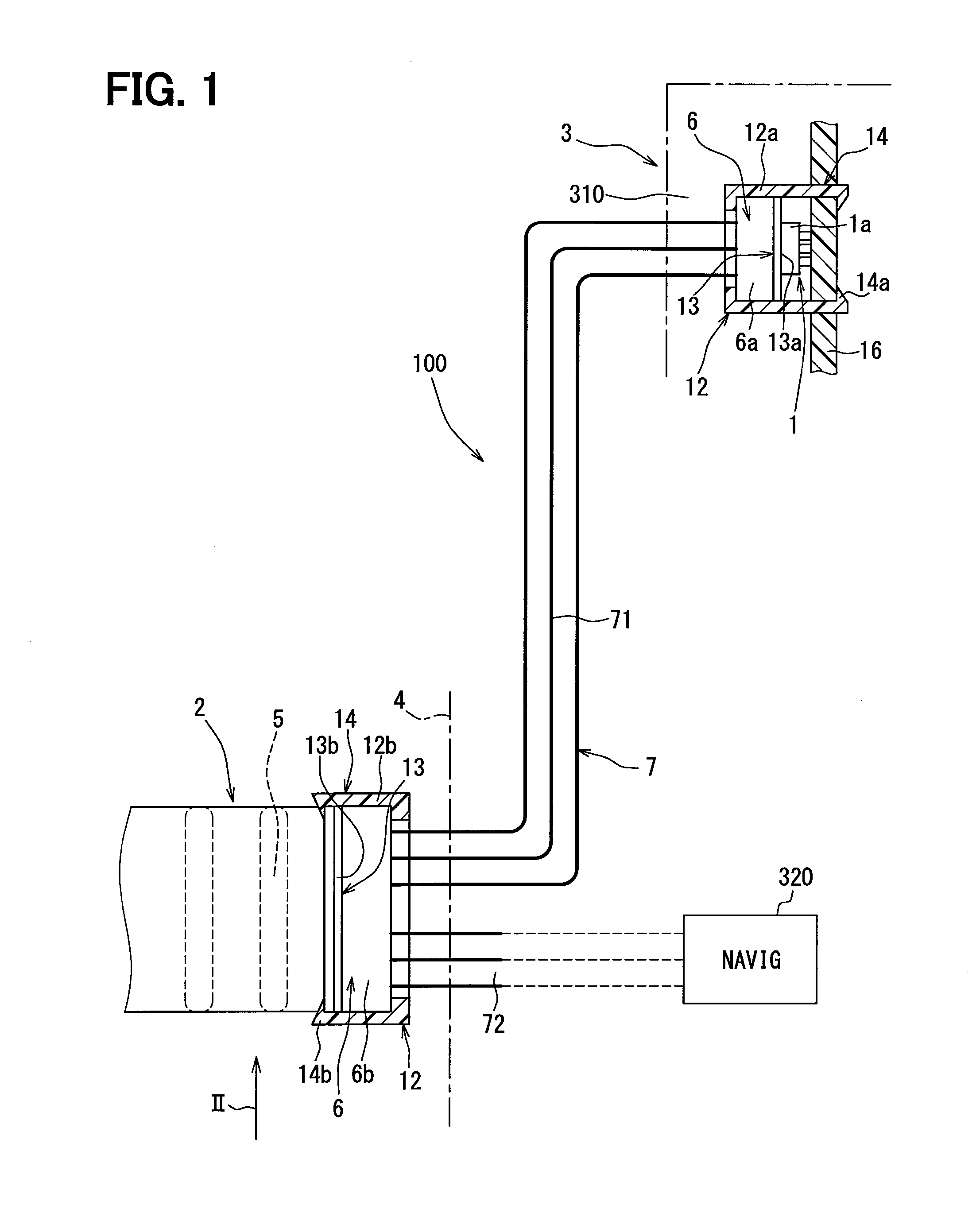
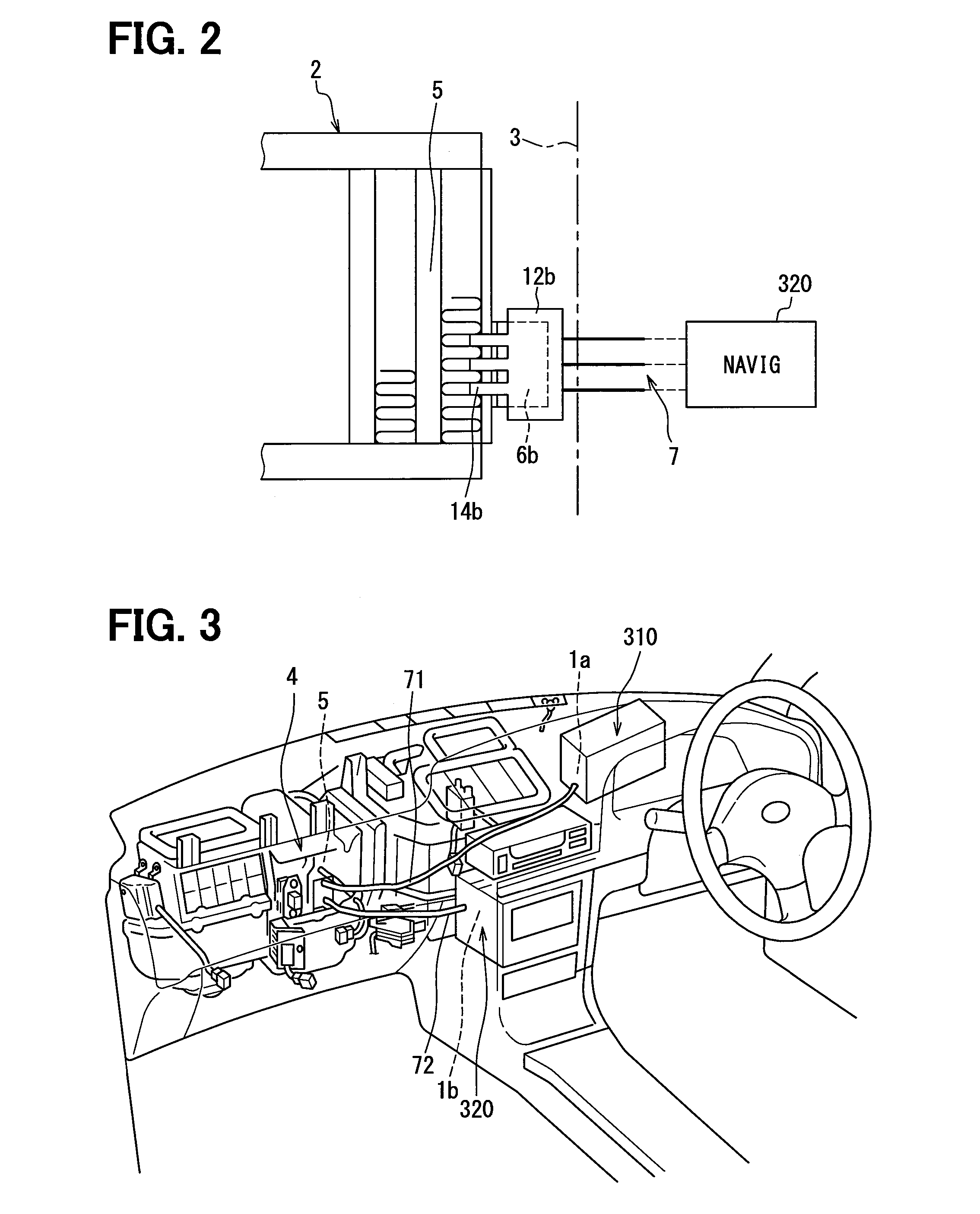
[0033]Hereinafter, a first embodiment of the present disclosure will be described in detail with reference to FIG. 1 to FIG. 4. FIG. 1 illustrates a heat transfer device 100 according to a first embodiment of the present disclosure. FIG. 2 illustrates a partial side of the heat transfer device 100 viewed in a direction indicated by an arrow II in FIG. 1. FIG. 3 illustrates a schematic configuration of a neighborhood of an instrument panel in a vehicle in which the heat transfer device 100 is installed.

[0034]Referring to FIGS. 1 and 2, a heat generation member 1 that generates heat is formed of a semiconductor device in a head-up display 310 serving as an electronic device 3 in a vehicle interior. A heat radiation member 2 that radiates the heat is formed of an evaporator 5 in a vehicle air conditioning apparatus 4. The evaporator 5 configures a single heat radiation member 2 for multiple heat generation members 1. Another heat generation member 1 is formed of a semiconductor device ...

second embodiment

[0063]Next, a second embodiment of the present disclosure will be described. In the following respective embodiments, the same components as those in the above-mentioned first embodiment are denoted by identical reference numerals, and will be omitted from a description, and different configurations will be described. Incidentally, in the second and subsequent embodiments, the same reference numerals as those in the first embodiment denote identical configurations, and a preceding description is incorporated. FIG. 5 illustrates a schematic configuration of a heat transfer device according to a second embodiment of the present disclosure.

[0064]An evaporator 5 in a vehicle air conditioning apparatus configures a heat radiation member 2 for a heat generation member 1. The heat generation member 1 is, for example, formed of a semiconductor device in a head-up display 310 (FIG. 3 described in the first embodiment) disposed inside of an instrument panel. The heat generation member 1 and t...

third embodiment

[0083]Next, a third embodiment of the present disclosure will be described. Portions different from those in the above embodiments will be described. FIG. 7 illustrates a schematic configuration of a connector on an electronic device side according to a third embodiment of the present disclosure. Referring to FIG. 7, a fixing member 12 configuring an outer shell of a connector internally houses a composite member 6, and a heat conductor 7 is led from a surface of the fixing member 12. A claw portion 14 coupled with a circuit board 16 of a semiconductor device 1 a configuring a heat generation member 1 is provided on the fixing member 12.

[0084]The fixing member 12 is coupled with the circuit board 16 by the claw portion 14, and the composite member 6 having a base material 8 is pressed against a surface of the semiconductor device 1 a configuring the heat generation member 1 through the interface substance 13. An electric heating element (for example, PTC) 23 that is energized by a b...


PUM


Abstract

A heat transfer device couples a heat generation member with a heat radiation member, and transfers heat from the heat generation member to the heat radiation member. The heat transfer device includes a composite member and a heat conductor. The composite member includes multiple carbon nanotubes and multiple carbon fibers which are mixed into a base material and complexed together, and the respective carbon fibers are crosslinked with each other by the carbon nanotubes. The heat conductor has one flexible end embedded in the composite member. The embedded one end is crosslinked with the carbon fibers in the composite member through the carbon nanotubes.

Description

CROSS REFERENCE TO RELATED APPLICATION[0001]This application is based on and incorporates herein by reference Japanese Patent Application No. 2013-253324 filed on Dec. 6, 2013.TECHNICAL FIELD[0002]The present disclosure relates to a heat transfer device having a heat conductor that can transfer a heat between a heat generation member that is an object to be cooled and a heat radiation member that radiates the heat transferred from the heat generation member. In particular, the present disclosure relates to a heat transfer device that cools an electronic device in a vehicle interior, which serves as the heat generation member placed at a position separate from a vehicle air conditioning apparatus, by using the vehicle air conditioning apparatus.BACKGROUND ART[0003]In recent vehicles, electronic devices small in size and high in heat generation, such as a navigation apparatus, have been used. Cooling of heat generation units of those electronic devices is becoming increasingly importa...

Claims


Application Information

Patent Timeline
IPC IPC(8): B60H1/00F28F21/02B60H1/32
CPCB60H1/00271B60H1/3227F28F21/02B60H1/2215F28F2255/20F28F2013/006F28F2013/001B60H1/00985H01L23/373H05K7/2039H01L2924/0002B60H1/22B60R16/02B60H2001/229H05K7/20418H01L2924/00
Inventor ITO, KOJIITO, KOICHI
Owner DENSO CORP
Why Eureka
Try Eureka