Image processing method and image processing apparatus

a processing method and image technology, applied in the field of image processing techniques, can solve the problems of difficult to obtain an image with high quality, difficult to obtain an image with a high contrast in bright field imaging, etc., and achieve the effect of simple apparatus configuration and simple image processing

Active Publication Date: 2017-01-05
DAINIPPON SCREEN MTG CO LTD
View PDF3 Cites 9 Cited by
  • Summary
  • Abstract
  • Description
  • Claims
  • Application Information

AI Technical Summary

Benefits of technology

[0015]According to the invention, it is possible to generate a difference image from two original images specified by a profile of contrast values of a plurality of images imaged with a focus position changed in a multi-stage manner. Thus, it is not necessary to obtain the focus position and an apparatus configuration for performing phase difference imaging is unnecessary. Therefore, an image with clear contours of cells can be generated by a simple apparatus configuration and a simple image processing.
[0016]The above and further objects and novel features of the invention will more fully appear from the following detailed description when the same is read in connection with the accompanying drawing. It is to be expressly understood, however, that the drawing is for purpose of illustration only and is not intended as a definition of the limits of the invention.

Problems solved by technology

However, since cytoplasm of the undyed cells are almost colorless and transparent, it is difficult to obtain an image with high quality.
Particularly, it is difficult to obtain an image with a high contrast in bright field imaging.

Method used


Image

  • Image processing method and image processing apparatus
  • Image processing method and image processing apparatus
  • Image processing method and image processing apparatus

Examples


first embodiment

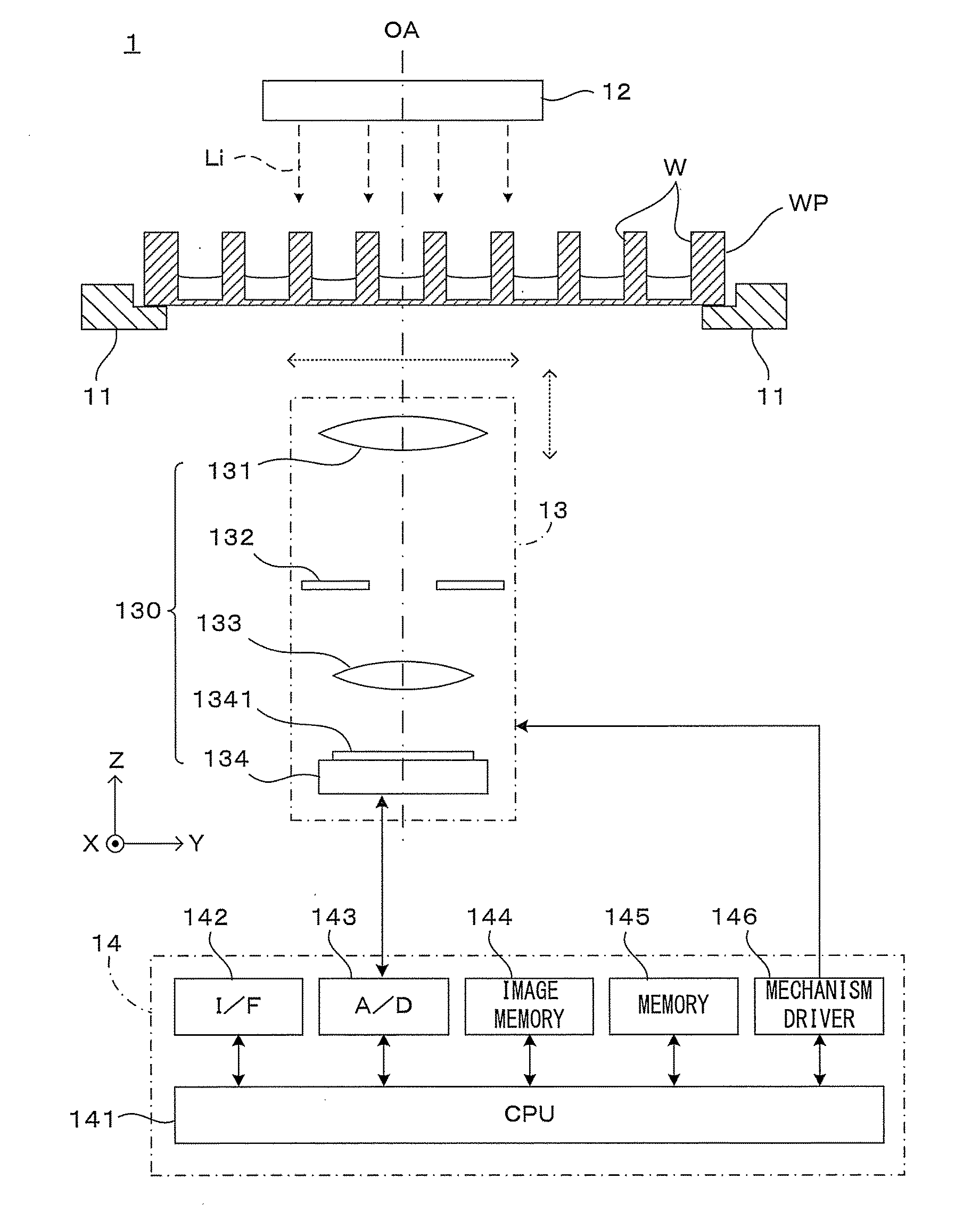
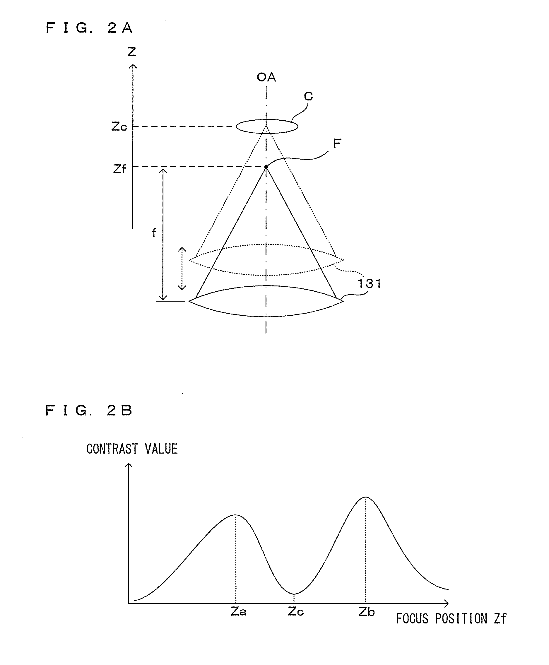
[0054]In the process of the first embodiment shown in FIG. 5A, two local maximum values of the contrast value in the profile are detected (Step S201). The local maximum value can be detected, for example, by obtaining a point of change from a contrast value increasing phase to a contrast value decreasing phase as the set value of the focus position changes in the profile. Then, the set values of two focus positions giving these local maximum values are obtained (Step S202). These two set values are supposed to be values close to the values Za, Zb in FIG. 2B.

[0055]Two original images respectively corresponding to the two local maximum values obtained in this way are extracted, a pixel value difference is obtained for each pixel between those original images, and the constant K as an offset value is added. In this way, the pixel value of each pixel constituting the difference image is obtained (Step S203). By reconfiguring an image in which the pixels having the obtained pixel values ...

second embodiment

[0060]FIGS. 6A and 6B are a graph and a table more specifically showing the difference image generation process in the In this embodiment, a set value Zm giving a local minimum value is obtained in the profile of the image contrast value in relation to the set value of the focus position as shown in FIG. 6A. This value Zm is estimated to be a position near the focus position Zc shown in FIG. 2B, but both may not coincide. Two original images corresponding to positions respectively at a distance AZ from this position Zm in (+) and (−) directions are used as original images as a basis of the difference image.

[0061]According to the knowledge of the inventors of the application, a distance between the focus position giving the local minimum value of the contrast value and the focus position giving the local maximum value in the profile of the contrast value in relation to the focus position depends on the type of the cells C. Thus, this distance can be substantially predicted if the ty...


PUM


Abstract

An image processing apparatus includes a holder holding a carrier carrying cells, an imager including an imaging optical system in which an optical axis is oriented toward the carrier, and images the cells in a bright field, a position changer changing a focus position of the imaging optical system in a direction along the optical axis, a controller changing a set position of the focus position by the position changer and obtaining a plurality of original images by causing the imager to perform imaging at each set position, and an image processor calculating a contrast value of each original image, specifying two set positions at opposite sides of a local minimum value of the contrast value in a profile of the contrast value in relation to the set position and generating a difference image of two of the original images respectively imaged at the two set positions.

Description

CROSS REFERENCE TO RELATED APPLICATION[0001]The disclosure of Japanese Patent Application No. 2014-199857 filed on Sep. 30, 2014 including specification, drawings and claims is incorporated herein by reference in its entirety.TECHNICAL FIELD[0002]This invention relates to an image processing technique applied to an image obtained by imaging cells carried in a container and particularly to a technique for obtaining an image with clear contours of cells.BACKGROUND ART[0003]In medical and bioscience experiments, cells as an observation object have been imaged by a CCD camera or the like and converted into data, and various image processing techniques have been applied to this image data for observation and analysis. Conventionally, cells have been dyed using a dye to enhance the visibility of the cells. To suppress damage given to the cells, it is required to image the cells without dyeing them in some cases. However, since cytoplasm of the undyed cells are almost colorless and transpa...

Claims


Application Information

Patent Timeline
Patent Type & Authority Applications(United States)
IPC IPC(8): G02B21/36G02B7/36G02B21/24G06T5/50G06T7/60
CPCG02B7/36G02B21/241G02B21/367G06T5/50G06T7/60G06T2207/10056G06T2207/10148G06T2207/20192G06T2207/20224G06T2207/30024G06T2207/30242
Inventor SUEKI, HIROSHIKOBAYASHI, MASAYOSHIFUJIMOTO, HIROKI
Owner DAINIPPON SCREEN MTG CO LTD
Why Eureka
Try Eureka