Systems and methods for generating depth maps using a camera arrays incorporating monochrome and color cameras

a camera array and depth map technology, applied in the field of image sensors, can solve the problems of limiting the maximum possible signal that can be captured, image sensors are subject to various performance constraints, etc., and achieve the effects of reducing noise, reducing overall thickness of camera array, and reducing thickness of lens elements

Active Publication Date: 2017-01-05
FOTONATION LTD +1
View PDF0 Cites 80 Cited by
  • Summary
  • Abstract
  • Description
  • Claims
  • Application Information

AI Technical Summary

Benefits of technology

[0013]In one embodiment, lens elements are provided to direct and focus light onto the imagers. Each lens element focuses light onto one imager. Because each lens element is associated with one imager, each lens element may be designed and configured for a narrow light spectrum. Further, the thickness of the lens element may be reduced, decreasing the overall thickness of the camera array. The lens elements are fabricated using wafer level optics (WLO) technology.
[0014]In one embodiment, the plurality of imagers include at least one near-IR imager dedicated to receiving near-IR (Infrared) spectrum. An image generated from the near-IR imager may be fused with images generated from other imagers with color filters to reduce noise and increase the quality of the images.
[0015]In one embodiment, the plurality of imagers may be associated with lens elements that provide a zooming capability. Different imagers may be associated with lens of different focal lengths to have different fields-of-views and provide different levels of zooming capability. A mechanism may be provided to provide smooth transition from one zoom level to another zoom level.

Problems solved by technology

The image sensors are subject to various performance constraints.
The performance constraints for the image sensors include, among others, dynamic range, signal to noise (SNR) ratio and low light sensitivity.
Typically, the well capacity of an image sensor limits the maximum possible signal that can be captured by the image sensor.

Method used


Image

  • Systems and methods for generating depth maps using a camera arrays incorporating monochrome and color cameras
  • Systems and methods for generating depth maps using a camera arrays incorporating monochrome and color cameras
  • Systems and methods for generating depth maps using a camera arrays incorporating monochrome and color cameras

Examples


Embodiment Construction

[0027]A preferred embodiment of the present invention is now described with reference to the figures where like reference numbers indicate identical or functionally similar elements. Also in the figures, the left most digits of each reference number corresponds to the figure in which the reference number is first used.

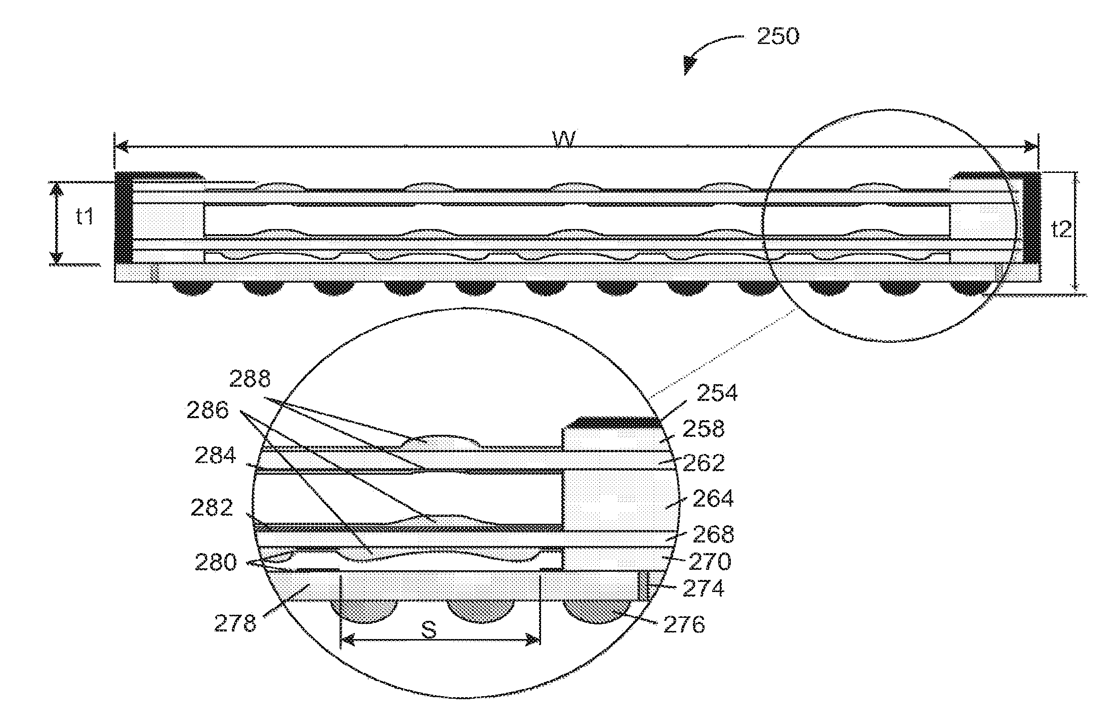
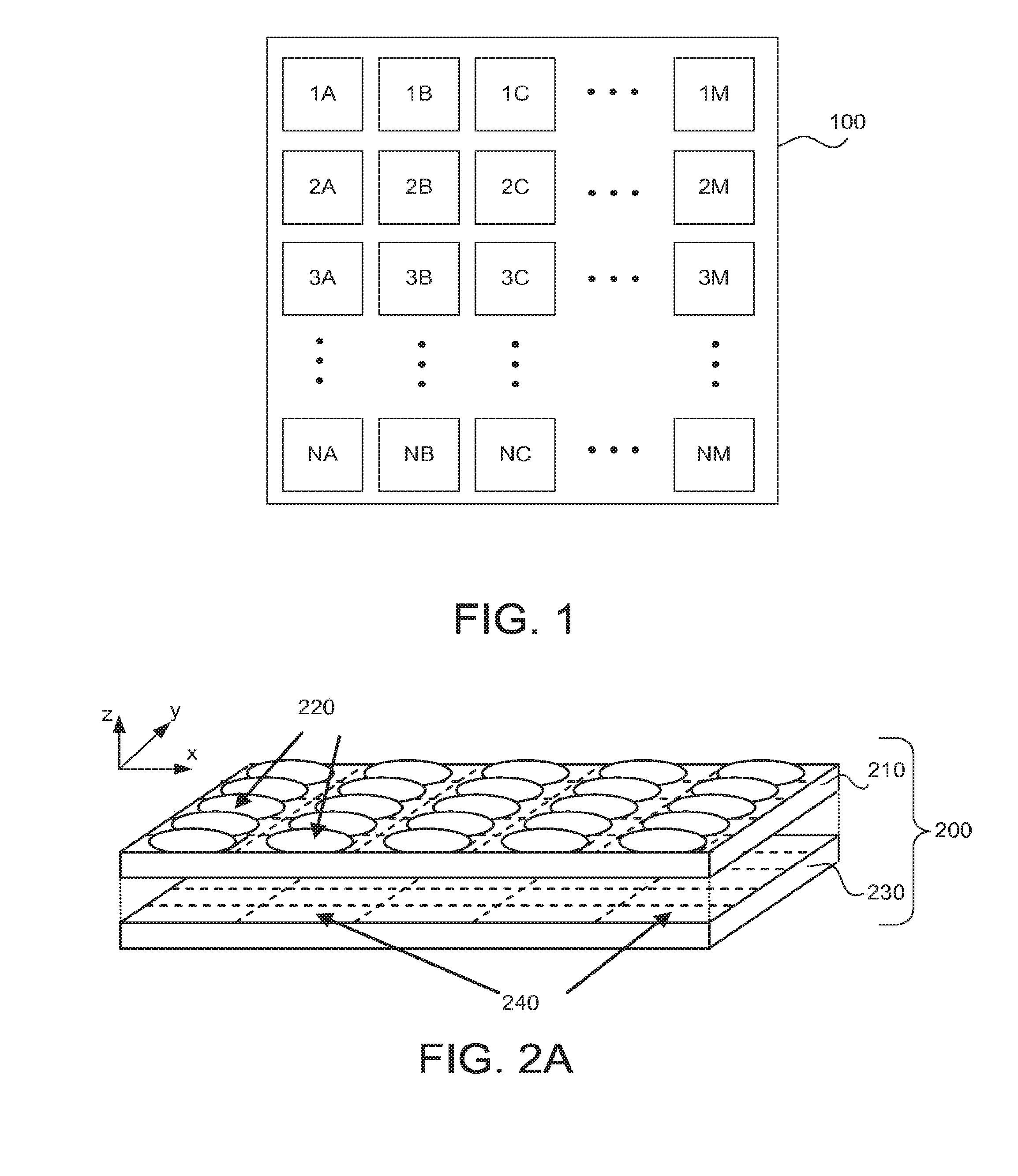
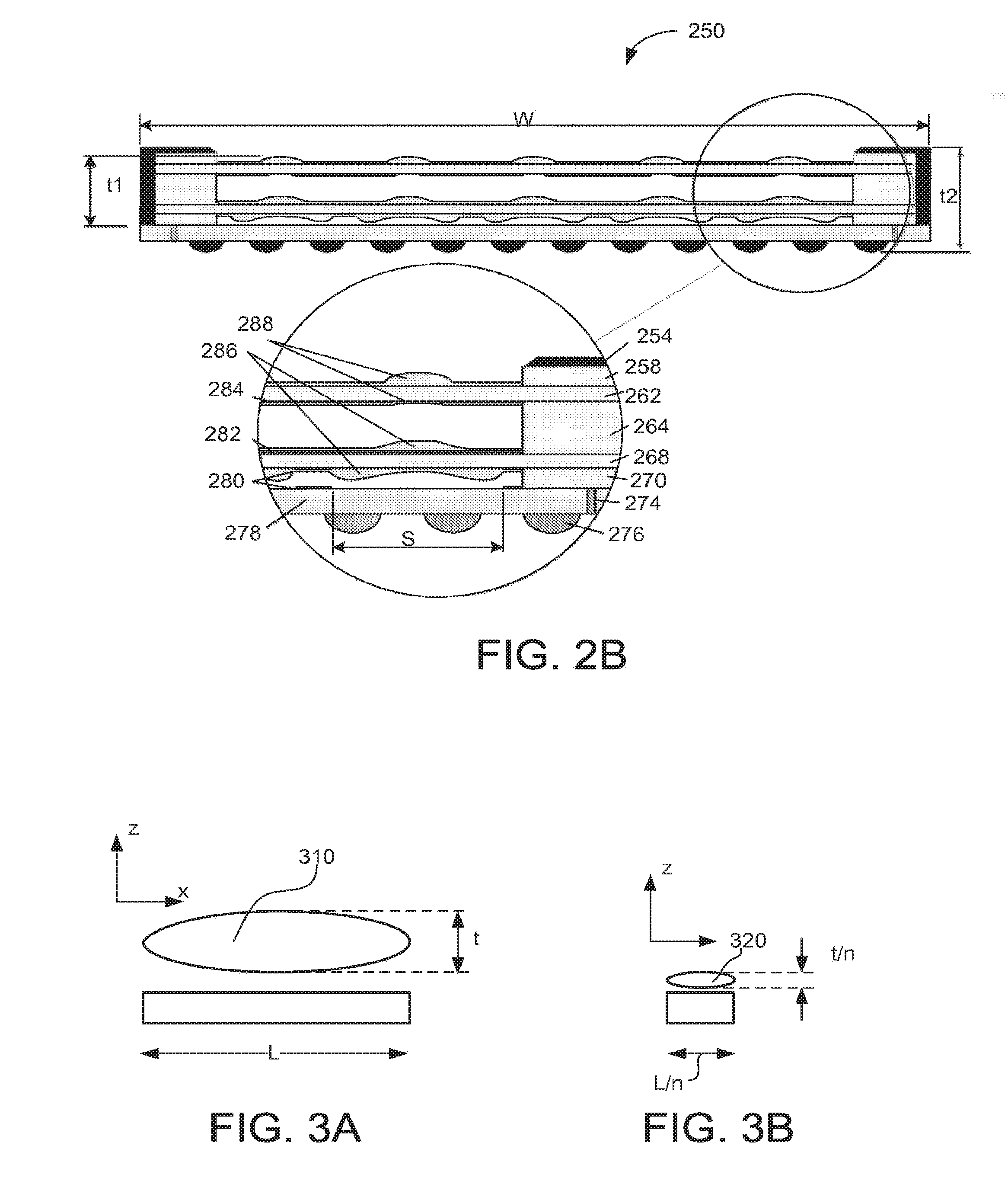
[0028]Embodiments relate to using a distributed approach to capturing images using a plurality of imagers of different imaging characteristics. Each imager may be spatially shifted from another imager in such a manner that an imager captures an image that us shifted by a sub-pixel amount with respect to another imager captured by another imager. Each imager may also include separate optics with different filters and operate with different operating parameters (e.g., exposure time). Distinct images generated by the imagers are processed to obtain an enhanced image. Each imager may be associated with an optical element fabricated using wafer level optics (WLO) technology...


PUM


Abstract

A camera array, an imaging device and / or a method for capturing image that employ a plurality of imagers fabricated on a substrate is provided. Each imager includes a plurality of pixels. The plurality of imagers include a first imager having a first imaging characteristics and a second imager having a second imaging characteristics. The images generated by the plurality of imagers are processed to obtain an enhanced image compared to images captured by the imagers. Each imager may be associated with an optical element fabricated using a wafer level optics (WLO) technology.

Description

RELATED APPLICATION[0001]This application is a continuation of U.S. patent application Ser. No. 15 / 095,930, entitled “Systems and Methods for Measuring Depth Using Images Captured by a Camera Array Including Cameras Surrounding a Central Camera”, filed Apr. 11, 2016, which is a continuation of U.S. patent application Ser. No. 14 / 988,670, entitled “Systems and Methods for Generating Depth Maps Using Light Focused on an Image Sensor by a Lens Element Array”, filed Jan. 5, 2016, which is a continuation of U.S. patent application Ser. No. 14 / 704,909, entitled Systems and Methods for Generating Depth Maps Using Light Focused on an Image Sensor by a Lens Element Array”, filed May 5, 2015, which is a continuation of U.S. patent application Ser. No. 14 / 475,466, entitled “Capturing and Processing of Near-IR Images Including Occlusions Using Camera Arrays Incorporating Near-IR Light Sources”, filed Sep. 2, 2014, which application is a continuation of U.S. patent application Ser. No. 12 / 935,50...

Claims


Application Information

Patent Timeline
Patent Type & Authority Applications(United States)
IPC IPC(8): H04N5/247G06T7/00H04N5/265H04N5/232H04N5/225H01L27/146H04N1/195G02B5/20G02B3/00G02B13/00G02B27/00H04N9/04H04N5/355
CPCH01L27/14618H01L27/14625H04N1/195H04N1/19589H01L2924/0002G06T2207/10052G06T7/557G06T7/70G06T7/55G06T7/50H04N13/128H04N13/243H04N13/257H01L27/14632H01L27/14685H01L27/14687H01L27/14621H04N1/19594H04N23/60H04N23/69H04N25/41H04N25/131H04N25/135H04N25/134H01L2924/00H04N5/265H04N23/40H04N23/45H04N23/54H04N23/55H04N23/67H04N23/80H04N23/698H04N25/00H04N25/702H04N23/90H04N23/10H04N23/951H04N25/60H04N25/74H04N25/534H04N25/581H04N25/616H04N2013/0081G06T3/4053H04N5/33H04N5/262H04N5/2621G02B5/20G02B13/0015G02B27/1066G02B27/123G06T1/20G02B3/0006G02B5/208G02B13/0085G02B27/0025G06T2207/30244
Inventor VENKATARAMAN, KARTIKJABBI, AMANDEEP S.MULLIS, ROBERT H.
Owner FOTONATION LTD
Why Eureka
Try Eureka