
Engine device

a technology of engine and cylinder body, which is applied in the direction of machines/engines, mechanical equipment, transportation and packaging, etc., can solve the problems of incomplete chemical reaction such as the regeneration of a diesel particulate filter or a selective catalyst reducing action, the temperature of the exhaust gas supplied, and the dimensional error of the working dimension, so as to improve the assembly workability of the exhaust gas purification unit, easy to move, and easy to dissolve the effect of working dimensional errors

Active Publication Date: 2017-01-12
YANMAR POWER TECHNOLOGY CO LTD
View PDF3 Cites 5 Cited by
  • Summary
  • Abstract
  • Description
  • Claims
  • Application Information

AI Technical Summary

Benefits of technology

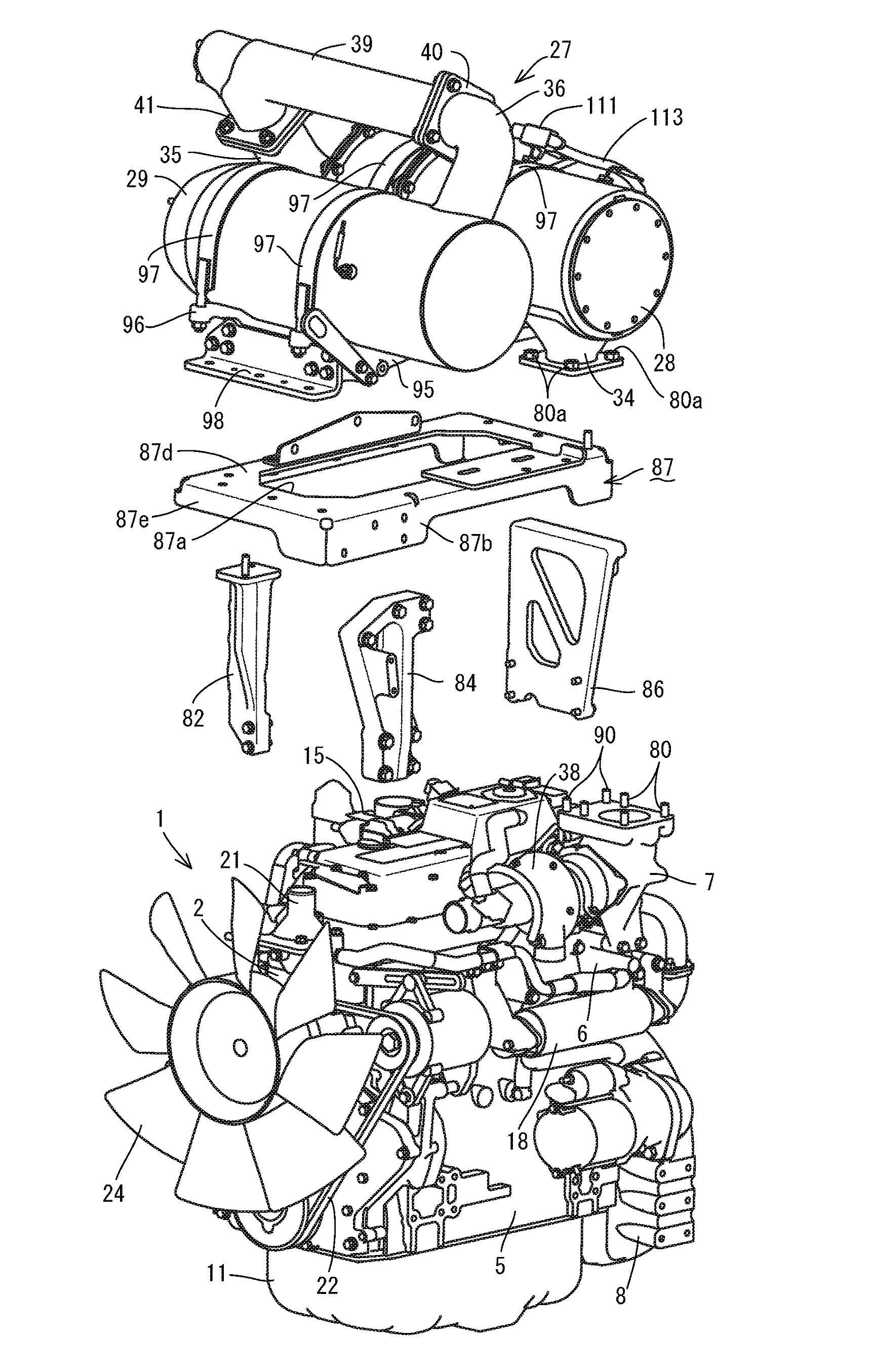
The invention relates to an engine device that includes a first case to remove particulate matters and a second case to remove nitrogen oxides from exhaust gas. The device includes a support base connected to the engine, and the first and second cases are arranged in the support base. The support structure for the cases is separated into a support portion (the support base) and support post portions (a plurality of support leg bodies). The first and second cases can be well maintained at an outer peripheral portion of the engine while reducing interference with the attached part of the engine. The assembly and maintenance workabilities of the engine are improved. The support base is firmly fixed to the exhaust gas outlet pipe, making it easy to connect the exhaust gas purification device to the main engine. This improves the assembly workability of the device.

Problems solved by technology

According to Japanese Unexamined Patent Publication No. 2009-74420, Japanese Unexamined Patent Publication No. 2012-21505, and Japanese Unexamined Patent Publication No. 2013-104394, in the case that the DPF case and the SCR case are assembled away from the engine, the temperature of the exhaust gas supplied from the engine to the DPF case or the SCR case has been conventionally lowered, and a chemical reaction such as regeneration of a diesel particulate filter or a selective catalyst reducing action has tended to be incomplete.
Accordingly, there has been conventionally a problem that, for example, a special device for keeping the temperature of the exhaust gas in the SCR case at a high temperature is necessary.
However, it is necessary to form an attaching surface of the subject to be installed into a horizontal shape (a flat shape), and there is a problem that, for example, a support attitude of the DPF case and the SCR case is hard to be set to a predetermined attitude due to a working error of the attachment part such as the base frame.
As a result, there is a problem that, for example, the DPF case and the SCR case can not be supported compactly as well as an engine room is hard to be constructed compactly.
As a result, there is a problem, for example, that the DPF case, the SCR case, or the like can not be supported compactly as well as an engine room is hard to be constructed compact.
Further, there is a problem, for example, that an assembly workability, a maintenance workability, or the like of the DPF case, the SCR case, or the like can not be improved, in the engine room which is restricted its magnitude.

Method used


Image

  • Engine device
  • Engine device
  • Engine device

Examples


Embodiment Construction

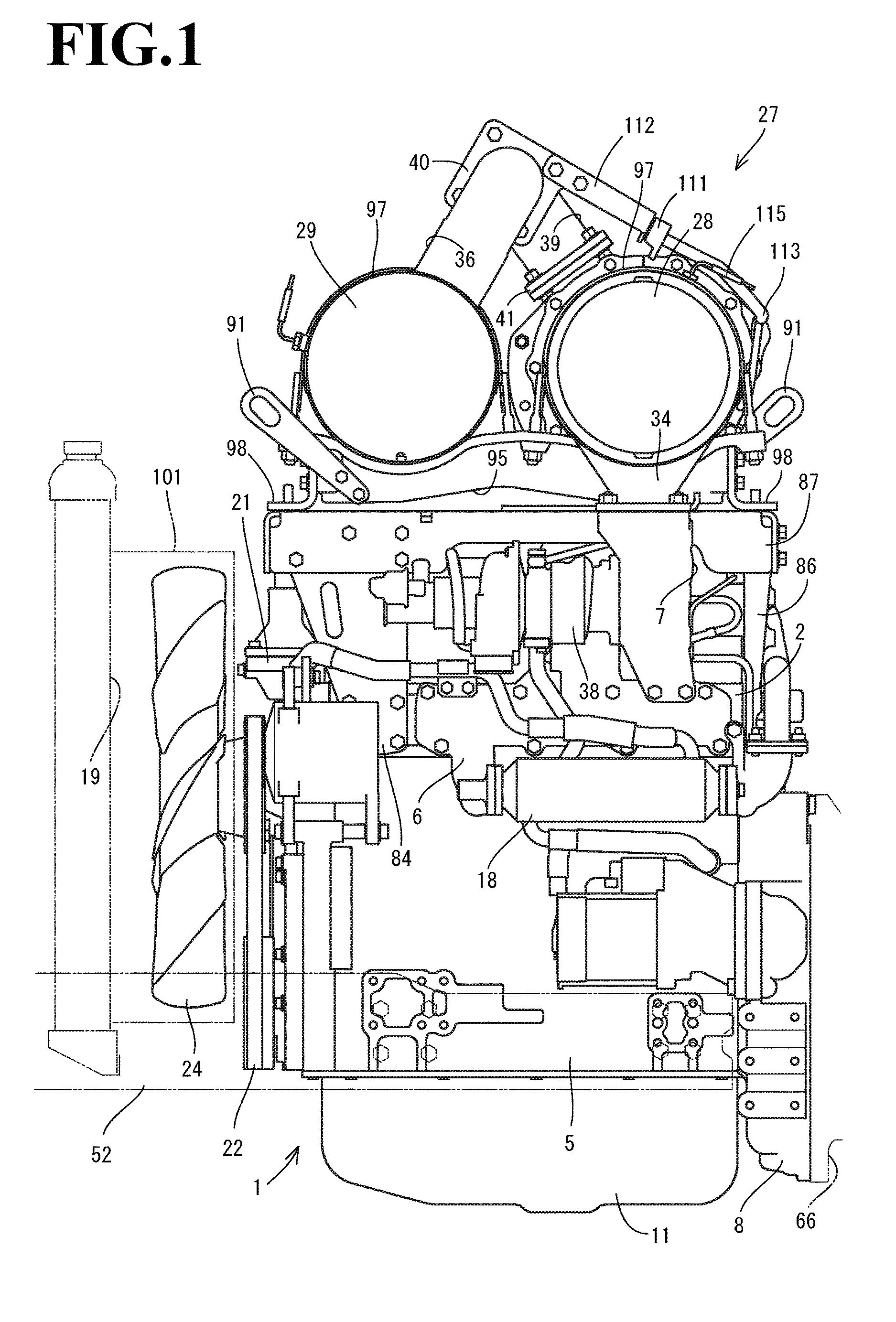
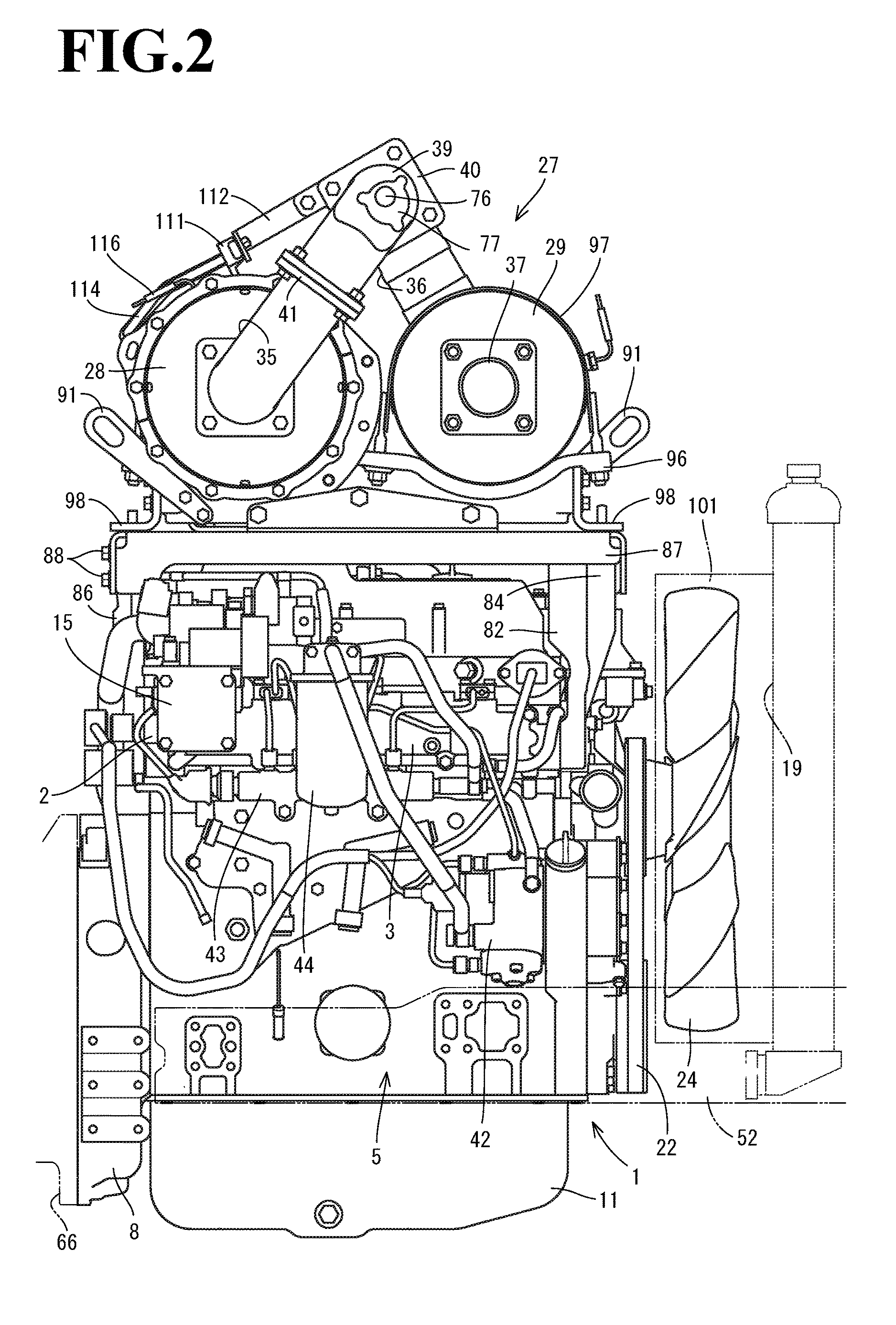
[0061]A description will be given below of a first embodiment obtained by embodying the present invention with reference to the accompanying drawings (FIGS. 1 to 12). FIG. 1 is a left side elevational view of a diesel engine 1 in which an exhaust manifold 6 is installed, FIG. 2 is a right side elevational view of the diesel engine 1 in which an intake manifold 3 is installed, and FIG. 3 is a front elevational view of the diesel engine 1 in which a cooling fan 24 is installed. A side in which the exhaust manifold 6 is installed is called as a left side surface of the diesel engine 1, a side in which the intake manifold 3 is installed is called as a right side surface of the diesel engine 1, and a side in which the cooling fan 24 is installed is called as a front surface of the diesel engine 1. A description will be given of an overall structure of the diesel engine 1 with reference to FIGS. 1 to 8.

[0062]As shown in FIGS. 1 to 7, an intake manifold 3 is arranged in one side surface of...


PUM


Abstract

The engine device has a first case which removes particulate matters in exhaust gas of the engine, and a second case which removes nitrogen oxides in the exhaust gas of the engine. The second case is connected to the first case via a urea mixing pipe. The engine device is provided with a plurality of support leg bodies which are connected their one end sides to the engine, and a support base which is connected to a plurality of support leg bodies. The first case and the second case are arranged in the support base.

Description

CROSS-REFERENCE TO RELATED APPLICATIONS[0001]The present application is a continuation application of International Application No. PCT / JP2015 / 56961, filed Mar. 10, 2015, which claims priority to Japanese Patent Application No. 2014-59115, filed Mar. 20, 2014, Japanese Patent Application No. 2014-59116, filed Mar. 20, 2014, and Japanese Patent Application No. 2014-65696, filed Mar. 27, 2014. The contents of these applications are incorporated herein by reference in their entirety.BACKGROUND OF THE INVENTION[0002]The present invention relates to an engine device.[0003]In a working vehicle such as the tractor or the wheel loader, an opening and closing fulcrum shaft was arranged in a rear portion of a hood for covering an engine and the hood was rotated around the opening and closing fulcrum shaft, for streamlining a maintenance work of the engine which was arranged in a front portion of a travel machine body. Further, there has been conventionally known a technique of purifying the e...

Claims


Application Information

Patent Timeline
Patent Type & Authority Applications(United States)
IPC IPC(8): F01N3/20F01N13/00F01N3/021
CPCF01N3/2066F01N2610/02F01N13/009F01N3/021B60K13/04E02F9/0866F01N13/1805F01N13/1855F01N2250/02F01N2450/24F01N2590/08F01N2610/14B60K11/04B60Y2200/22B60Y2200/221B60Y2200/41B60Y2200/412F01N3/103F01N13/18F01N13/1844F01N13/0097Y02A50/20Y02T10/12
Inventor KIMURA, TOMOYUKISANDOU, YOSHIYUKI
Owner YANMAR POWER TECHNOLOGY CO LTD
Learn More