Working vehicle
- Summary
- Abstract
- Description
- Claims
- Application Information
AI Technical Summary
Benefits of technology
Problems solved by technology
Method used
Image
Examples
first embodiment
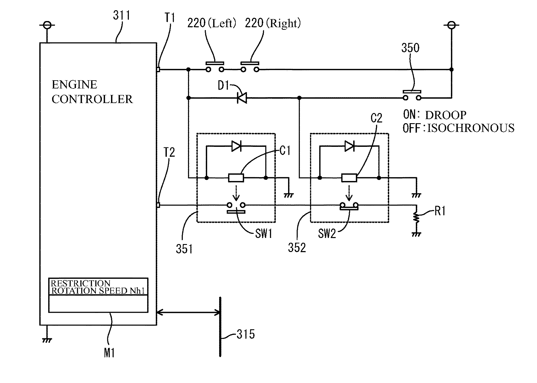
[0102]FIG. 17 shows a circuit block diagram. The engine controller 311 is provided with a droop switching terminal (a control mode switching terminal) T1 and a high-idle restriction terminal T2 as shown in FIG. 17, and stores a high-idle restriction rotation speed Nh1 in a memory M1. The droop switching terminal T1 is connected to a cathode of a diode D1 for preventing backflow, and a power supply voltage is applied to an anode of the diode D1 via the control mode selection switch 350. The right and left brake pedal switches 220 and 220 are connected in series. Further, a series circuit constituted by the brake pedal switch 220 and 220 is connected in parallel to a series circuit constituted by the diode D1 and the control mode selection switch 350.
[0103]One end of an electromagnetic coil C1 of an electromagnetic switch 351 is connected to a connection node between the droop switching terminal T1 and the cathode of the diode D1, and one end of an electromagnetic coil C2 of an electr...
second embodiment
[0142]FIG. 22 shows the circuit block diagram. In the present embodiment, the meter controller 312 may be provided with a droop switching terminal (a control mode switching terminal) Tm1 and a high-idle switching terminal Tm2, as shown in FIG. 22. Further, the engine controller 311 stores in a memory M1 high-idle restriction rotation speeds Nh1 and Nh2. The engine controller 311 stores the high-idle restriction rotation speed Nh1 as a restriction rotation speed at the isochronous control time, and stores the high-idle restriction rotation speed Nh2 as a restriction rotation speed at the droop control time.
[0143]The droop switching terminal Tm1 of the meter controller 312 is connected to a cathode of a diode Dm1 for preventing backflow, and is grounded to an anode of the diode Dm1 via the control mode selection switch 350. The right and left brake pedal switches 220 and 220 are connected in series. Further, a series circuit by the brake pedal switches 220 and 220 is connected in para...
third embodiment
[0149]FIG. 23 shows the circuit block diagram. In the present embodiment, the meter controller 312 may be provided with the droop switching terminal (the control mode switching terminal) Tm1 and the high-idle restriction terminal Tm3, as shown in FIG. 23. Further, the engine controller 311 stores only the high-idle restriction rotation speed Nh1 in the memory M1. Further, the control mode selection switch 350 is a single pole double throw switch in which a common terminal B1 is grounded, a selection terminal A1 is connected to the cathode of the diode Dm1, and a selection terminal A2 is connected to the high-idle restriction terminal Tm3 of the meter controller 312. The anode of the diode Dm1 is connected to the droop switching terminal Tm1 of the meter controller 312, and the right and left brake pedal switches 220 and 220 are connected in series between the droop switching terminal Tm1 and the earth potential.
[0150]The meter controller 312 informs the engine controller 311 via the...
PUM
 Abstract
Description
Claims
Application Information
 - R&D
- Intellectual Property
- Life Sciences
- Materials
- Tech Scout
- Unparalleled Data Quality
- Higher Quality Content
- 60% Fewer Hallucinations
Browse by: Latest US Patents, China's latest patents, Technical Efficacy Thesaurus, Application Domain, Technology Topic, Popular Technical Reports.
© 2025 PatSnap. All rights reserved.Legal|Privacy policy|Modern Slavery Act Transparency Statement|Sitemap|About US| Contact US: help@patsnap.com


