Vertical electric cooker and smoker and smoke box

a vertical electric cooker and smoker technology, applied in meat/fish preservation, food science, climate change adaptation, etc., can solve the problems of inconvenient use, inability to meet the needs of people, so as to reduce the temperature and heat transfer, eliminate the hot pockets within the smoke box, and reduce the effect of heat transfer

Active Publication Date: 2017-01-26
W C BRADLEY CO
View PDF4 Cites 11 Cited by
  • Summary
  • Abstract
  • Description
  • Claims
  • Application Information

AI Technical Summary

Benefits of technology

[0013]These features of the heating element assembly operate to (a) reduce the temperature and heat transfer at the bottom of the smoke box sufficiently to increase smoke time, (b) provide even heating of the wood chips in the entire lower layer inside the box so that the chips start at the same time, and (c) eliminate hot pockets within the smoke box.
[0014]In another aspect, an improved smoke box is provided for holding the wood chips or other pieces and slowly combusting the wood in an oxygen starved environment to produce wood smoke for use in the cooking and smoking chamber of the inventive apparatus. The smoke box has a false bottom which creates an internal gap in the container beneath the wood chips. In addition, either the lid of the smoke box, one or more vertical side walls of the box, or a combination thereof include(s) an exhaust flow assembly which defines a circuitous flow path wherein the smoke is required to flow through an inner flow gap (horizontal or vertical) and then change dir

Problems solved by technology

Because this reloading process may need to be repeated multiple times during a slow cooking and smoking cycle, a considerable amount of time and attention is required.
Also, the amount of smoke generated within the cooking chamber is cyclical such that (a) the amount of smoke generated for at least several minutes prior to replacing a spent load of wood chips can be undesirably low and (b) little or no smoke will be initially generated for several minutes after a fresh load of wood chips is inserted.
First, placing such a large amount of fuel in close proximity to the heat source can

Method used


Image

  • Vertical electric cooker and smoker and smoke box
  • Vertical electric cooker and smoker and smoke box
  • Vertical electric cooker and smoker and smoke box

Examples


embodiment 2

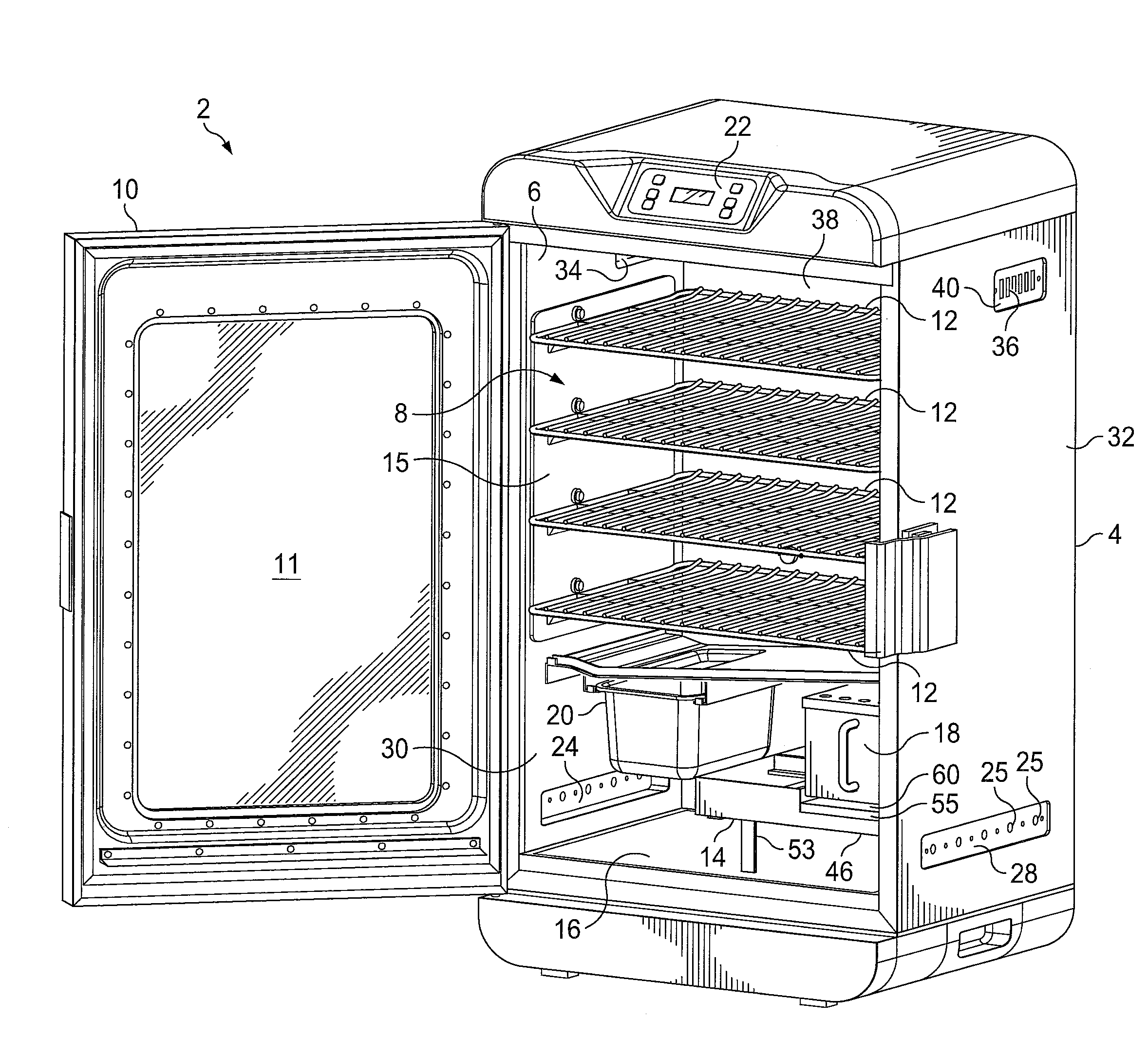
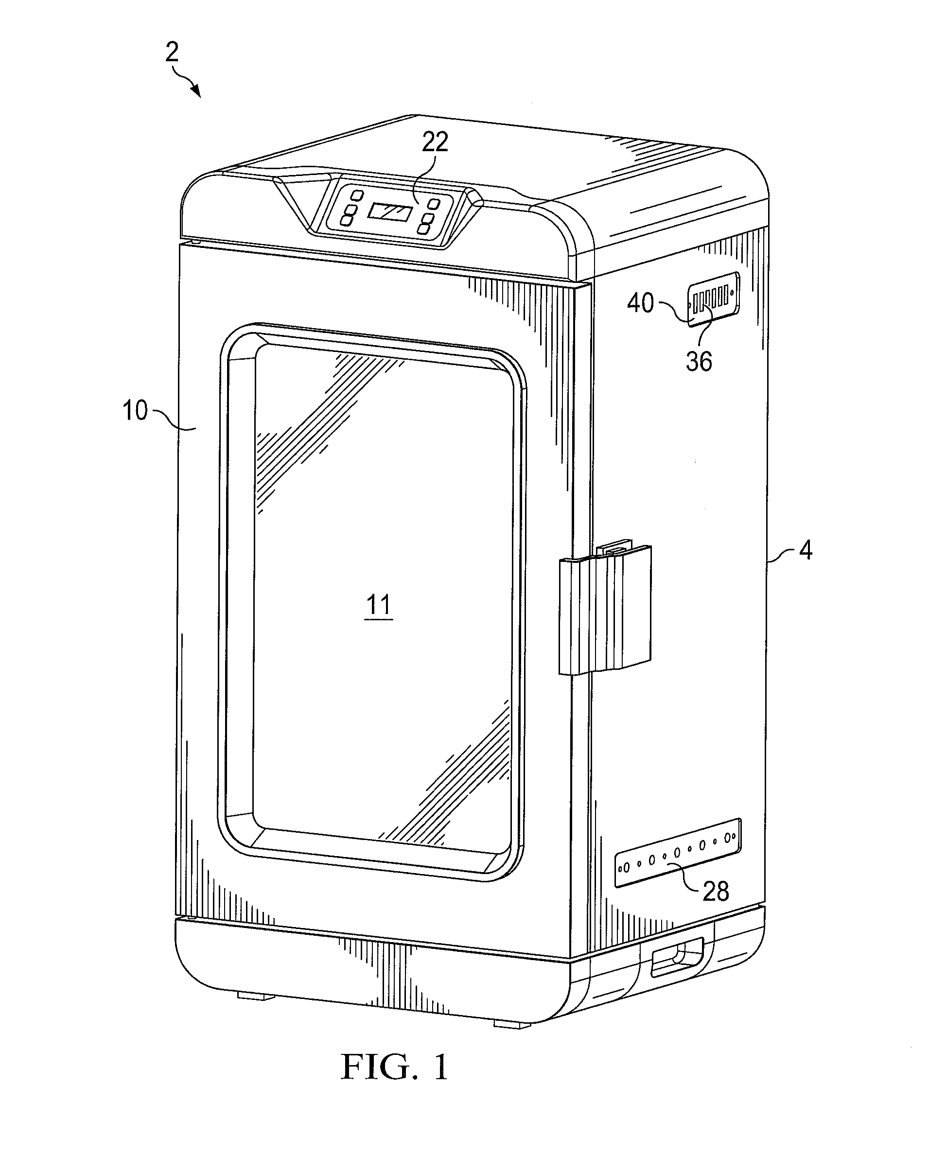
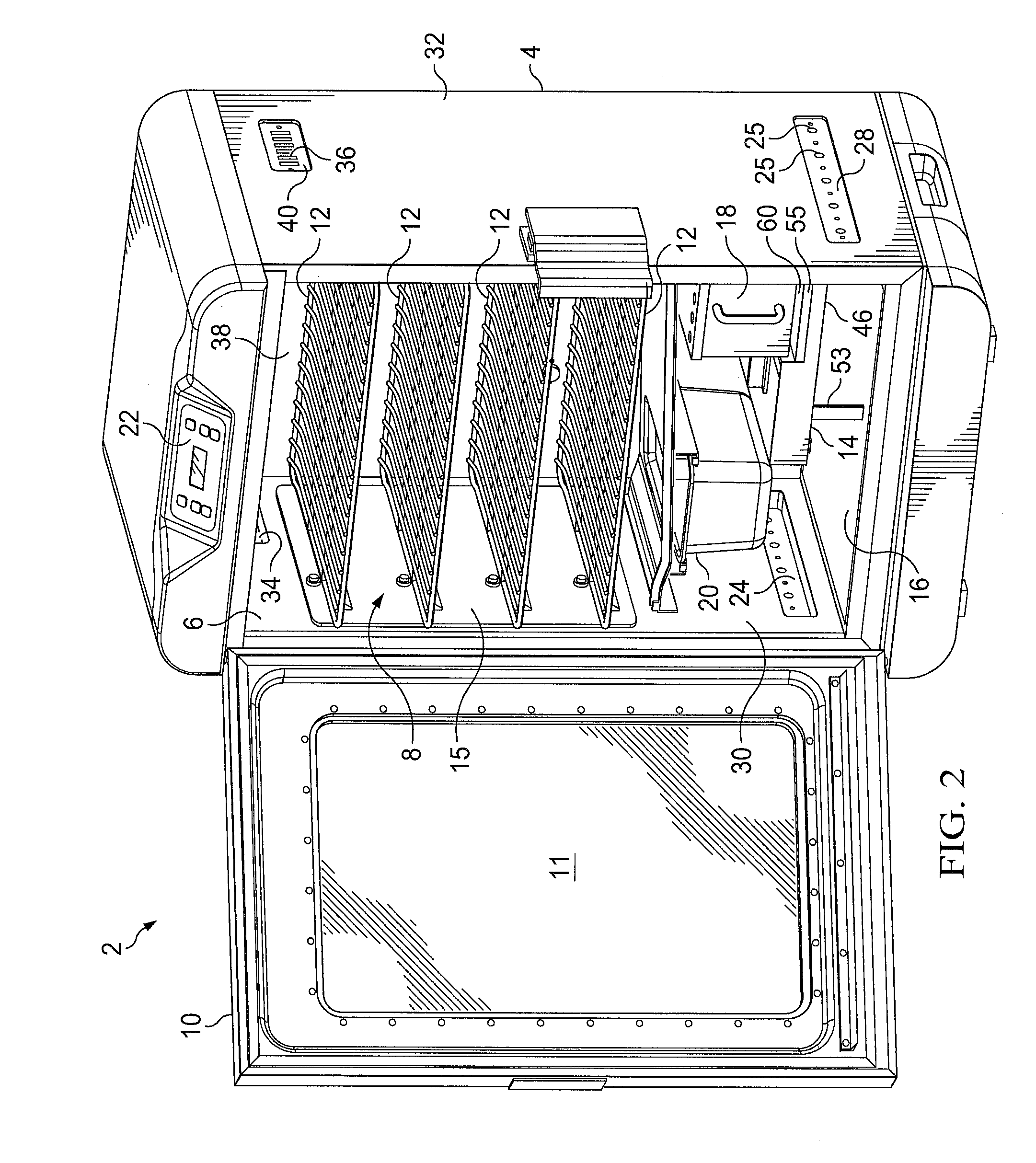
[0034]An embodiment 2 of the vertical electric cooker and smoker provided by the present invention is shown in FIGS. 1 and 2. The inventive electric cooking and smoking apparatus 2 comprises: a vertical rectangular box 4 having a vertical front opening 6; a cooking and smoking chamber 8 within the vertical box 4; a vertical front door 10, preferably having a window 11 therein, which is pivotably attached to the vertical box 4 for opening and sealingly closing the front opening 6 of the cooking and smoking chamber 8; a plurality of food support racks 12 removably positionable in the cooking and smoking chamber 8; an electrical heating element assembly 14 spaced above the floor 16 of the cooking and smoking chamber 8; a smoke box 18 which is removably positionable on the heating element assembly 14; a removable pan or other container 20 adjacent to the heating element assembly 14 for holding water or other liquid to maintain a desired level of moisture or flavorant vapor in the cookin...

embodiment 18

[0051]The embodiment 18 of the inventive smoke generating box used in the vertical electric cooking and smoking apparatus 2 is illustrated in FIGS. 3-6. The inventive smoke box 18 comprises: a rectangular box 75 having a longitudinal axis 76; a front handle 78; a cooling plate or “false bottom”80 which fits inside of the rectangular box 75; and a removable lid assembly 82. The false bottom 80 has a pair of downwardly extending side spacer rails 84 and 86 which support and space the false bottom 80 above the bottom 81 of the box 75 to provide and air gap 88 of from about 0.20 inches to about 0.50 inches, more preferably from about 0.33 inches to about 0.38 inches, between the false bottom 80 and the actual bottom 81 of the box 75. This additional air gap 88 within the bottom of the box 75 operates to further stabilize the heating of the wood chips or other wood pieces in the smoke box 18.

[0052]The rectangular box 75 will preferably be sized to contain at least four cups of wood chips...

embodiment 150

[0061]An alternative embodiment 150 of the inventive smoke box is illustrated in FIGS. 7 and 8. The inventive smoke box 150 is substantially the same as the inventive smoke box 18 except that rather than providing the circuitous exit path for the smoke through the lid of the box, a substantially similar flow path 152 is provided in one, two, three, or all four of the vertical sides 154, 156, 158, 160 of the inventive smoke box 150.

[0062]In the inventive smoke box 150, each of the one or more vertical sides having a circuitous smoke exit path 152 provided therein comprises: (a) an inner vertical wall 162 having a row of smoke openings 164 which extend across the upper end portion thereof; (b) an outer vertical wall 166 having an open upper end 168; (c) a middle vertical wall 170 positioned between the inner and outer vertical walls 162 and 166, and having a row of smoke openings 175 which extend across the bottom portion thereof; (d) an inner vertical flow gap 172 formed between the ...


PUM


Abstract

A vertical electric cooker and smoker having lower air intake vents and upper exhaust vents which together create a more balanced flow and distribution of smoke and reduce the operating pressure of the system to allow a much larger load of wood chips to be used without refilling. A smoke box is also provided for holding and properly combusting the larger quantity of wood chips in an oxygen deficient environment. The smoke box has a false bottom and discharges the smoke through a circuitous exhaust flow path. Also, the electric heating elements of the cooking and smoking apparatus are contained in an assembly which provides an air gap beneath the smoker box and also shields the smoker box to prevent the wood chips in the smoker box from becoming overheated.

Description

RELATED CASE[0001]This application claims the benefit of U.S. Provisional Patent Application Ser. No. 62 / 138,002 filed on Mar. 25, 2015 and incorporates said provisional application by reference into this document as if fully set out at this point.FIELD OF THE INVENTION[0002]The present invention relates to vertical electric apparatuses for cooking and smoking and to smoke generation devices and systems for such apparatuses.BACKGROUND OF THE INVENTION[0003]A vertical electric smoker typically comprises: a vertical box-type cooking and smoking chamber; a vertical front door for the cooking chamber; and an internal electric element. The electrical element is typically used for both (a) heating the interior of the cooking chamber for cooking the food and (b) heating a small amount of wood (e.g., wood chips, pellets, or other pieces) to generate smoke within the cooking chamber. Often the vertical box will be built with insulated walls, a window in the door, and electronic controls, inc...

Claims


Application Information

Patent Timeline
IPC IPC(8): A23B4/056A23B4/052
CPCA23B4/056A23V2002/00A23B4/052A23B4/048A23B4/0523A47J37/0629Y02A40/90
Inventor DIXON, WILLIAM A.ADALLAH, SLEIMAN ASSAADMCQUAGG, MARK STEPHEN
Owner W C BRADLEY CO
Why Eureka
Try Eureka