Supercharge Your Innovation With Domain-Expert AI Agents!

Method for manufacturing sintered magnet

a technology of manufactured sintered magnets and sintered magnets, which is applied in the manufacture of inductance/transformer/magnets, metal-working apparatuses, transportation and packaging, etc., can solve the problems of sintered magnet shape obtained, particle oxidation, coercive force and other magnetic properties may rather undergo deterioration, etc., and achieve high yield

Active Publication Date: 2017-01-26
DAIDO STEEL CO LTD
View PDF1 Cites 4 Cited by
  • Summary
  • Abstract
  • Description
  • Claims
  • Application Information

AI Technical Summary

Benefits of technology

The patent text explains that using a PLP method to make sintered magnets into a specific shape, such as cuboids, resulted in a higher probability of cracking and lower yield rates compared to making them into other shapes, like spheroids.

Problems solved by technology

Then, the surface area of the alloy powder particles as a raw material becomes large; as a result, the particles become vulnerable to oxidation.
When magnet alloys undergo oxidation, the coercive force and other magnetic properties thereof may rather undergo deterioration, or the magnet alloys may cause spontaneous ignition in the air.
In press methods, on the other hand, it is necessary to subject the alloy powder as a raw material to press molding, and the shape of sintered magnets obtained at the stage of having undergone the sintering process is limited to a shape having two parallel planes corresponding to a pair of punches in a press machine.
At the time when the sintering shrinkage occurs, friction arises between the sintered article and the mold.

Method used


Image

  • Method for manufacturing sintered magnet
  • Method for manufacturing sintered magnet
  • Method for manufacturing sintered magnet

Examples


examples

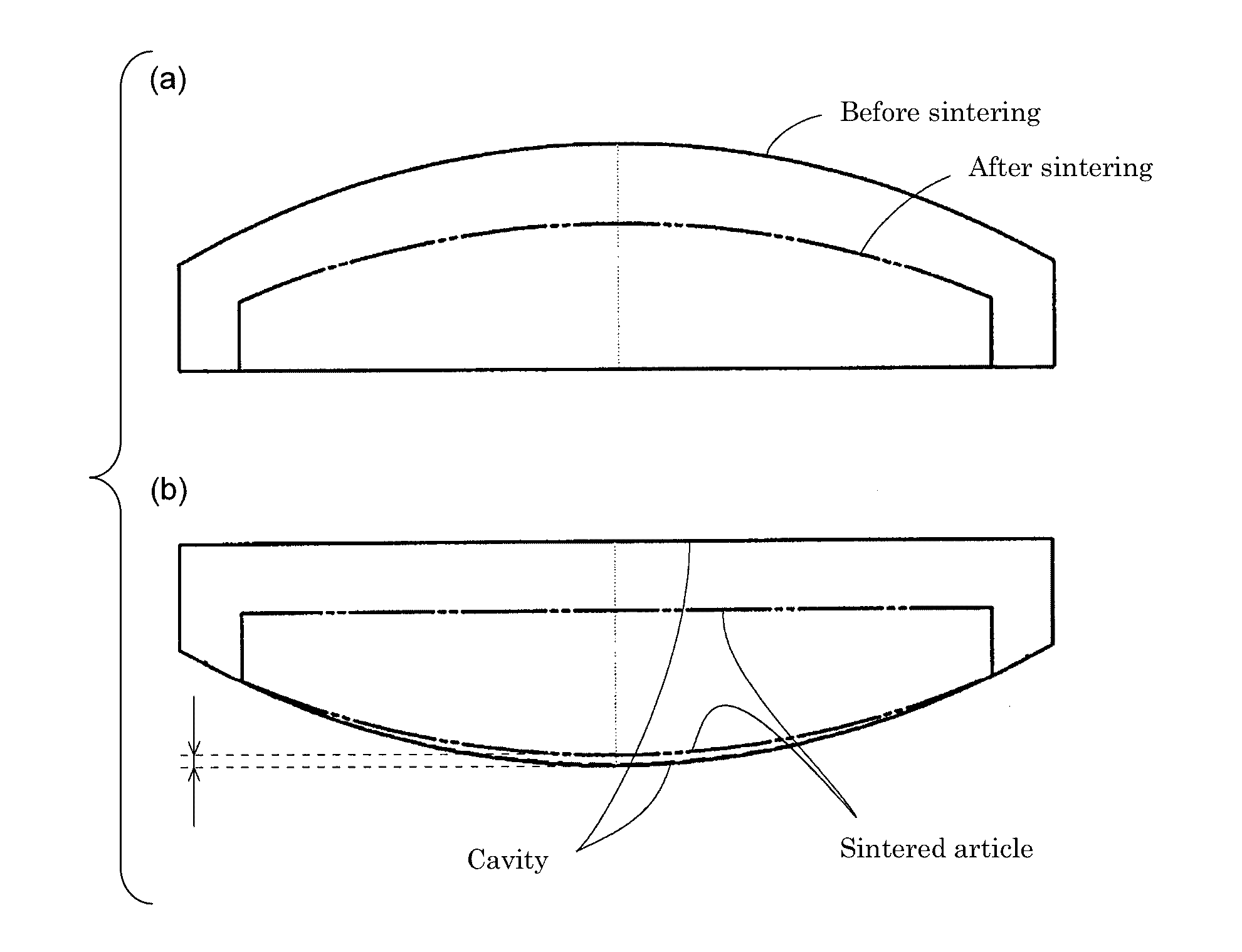
[0057]Experiments in the manufacture of RFeB base sintered magnets through the use of the foregoing methods, and simulation results thereof conducted are illustrated below.

[0058]In the experiments, two varieties of molds, one having cavities 13A and the other having cavities 13B, which are illustrated in (a) and (b) of FIG. 6, respectively, were used. The cavity 13A illustrated in (a) of FIG. 6, as with the cavity used in the simulation illustrated in FIG. 1, has a partially cylindrical face 131A and a flat face 133A opposite thereto. The cavity 13B illustrated in (b) of FIG. 6 has a curved face which is formed of a partially cylindrical face 131B and tapered portions 132B each of which is provided on either end of the face 131B and inclined toward a flat face 133B. At either end of the cavity 13B, the tapered portion 13213 intersects with the face 134B perpendicular to the flat face 133B. The tapered portions 132B are provided for the purpose of forming, in a sintered magnet to be ...


PUM

PropertyMeasurementUnit
pressureaaaaaaaaaa
temperatureaaaaaaaaaa
filling densityaaaaaaaaaa

Abstract

The present invention relates to a method for manufacturing a sintered magnet, using a mold provided with a main body having a cavity and a lid whose inner face is flat, and the method containing a filling process of filling alloy powder in the cavity and then mounting the lid on the main body, an orienting process of applying a magnetic field in a predetermined direction to the alloy powder in a state of being filled in the cavity, a sintering process of sintering the alloy povvder by heating in a state of being filled in the cavity after the orienting process, and a mold inverting process of turning the mold upside down which is carried out between the filling process and the orienting process or between the orienting process and the sintering process

Description

TECHNICAL FIELD[0001]The present invention relates to a method for manufacttithig sintered magnets usable for rotors or stators of motors.BACKGROUND ART[0002]In manufacturing sintered magnets, there has so far been adopted a method including filling a mold with alloy powder as a raw material (filling process), applying a magnetic field to the raw material alloy powder in the mold to orient particles of the raw material alloy powder (orienting process), applying pressure to the oriented raw material alloy powder to rnake a compression molded article (compression molding process), and performing sintering by heating the compression molded article after releasing the applied pressure (sintering process). Alternatively, there has been adopted a method in which, after the filling process, the orienting process and the compression molding process are carried out at the same time by applying pressure by the use of a press machine while applying a magnetic field to alloy powder as a raw mat...

Claims


Application Information

Patent Timeline
Patent Type & Authority Applications(United States)
IPC IPC(8): H01F41/02
CPCH01F41/0266B22F3/10B22F2999/00B22F1/14B22F2202/05
Inventor TOZAWA, YUSUKE
Owner DAIDO STEEL CO LTD
Features
  • R&D
  • Intellectual Property
  • Life Sciences
  • Materials
  • Tech Scout
  • Unparalleled Data Quality
  • Higher Quality Content
  • 60% Fewer Hallucinations
Learn More