Wireless high-density micro-electrocorticographic device

Inactive Publication Date: 2017-02-02
RGT UNIV OF CALIFORNIA
View PDF1 Cites 10 Cited by
  • Summary
  • Abstract
  • Description
  • Claims
  • Application Information

AI Technical Summary

Benefits of technology

[0010]Substantial improvements in neural implant longevity are needed to transition brain-machine interface (BMI) systems from research labs to clinical practice. While action potential (AP) recording through penetrating electrode arrays offers the highest spatial resolution, it comes at the price of tissue scarring, resulting in signal de

Problems solved by technology

While action potential (AP) recording through penetrating electrode arrays offers the highest spatial resolution, it comes at the price of tissue scarring, resulting in si

Method used


Image

  • Wireless high-density micro-electrocorticographic device
  • Wireless high-density micro-electrocorticographic device
  • Wireless high-density micro-electrocorticographic device

Examples


Example

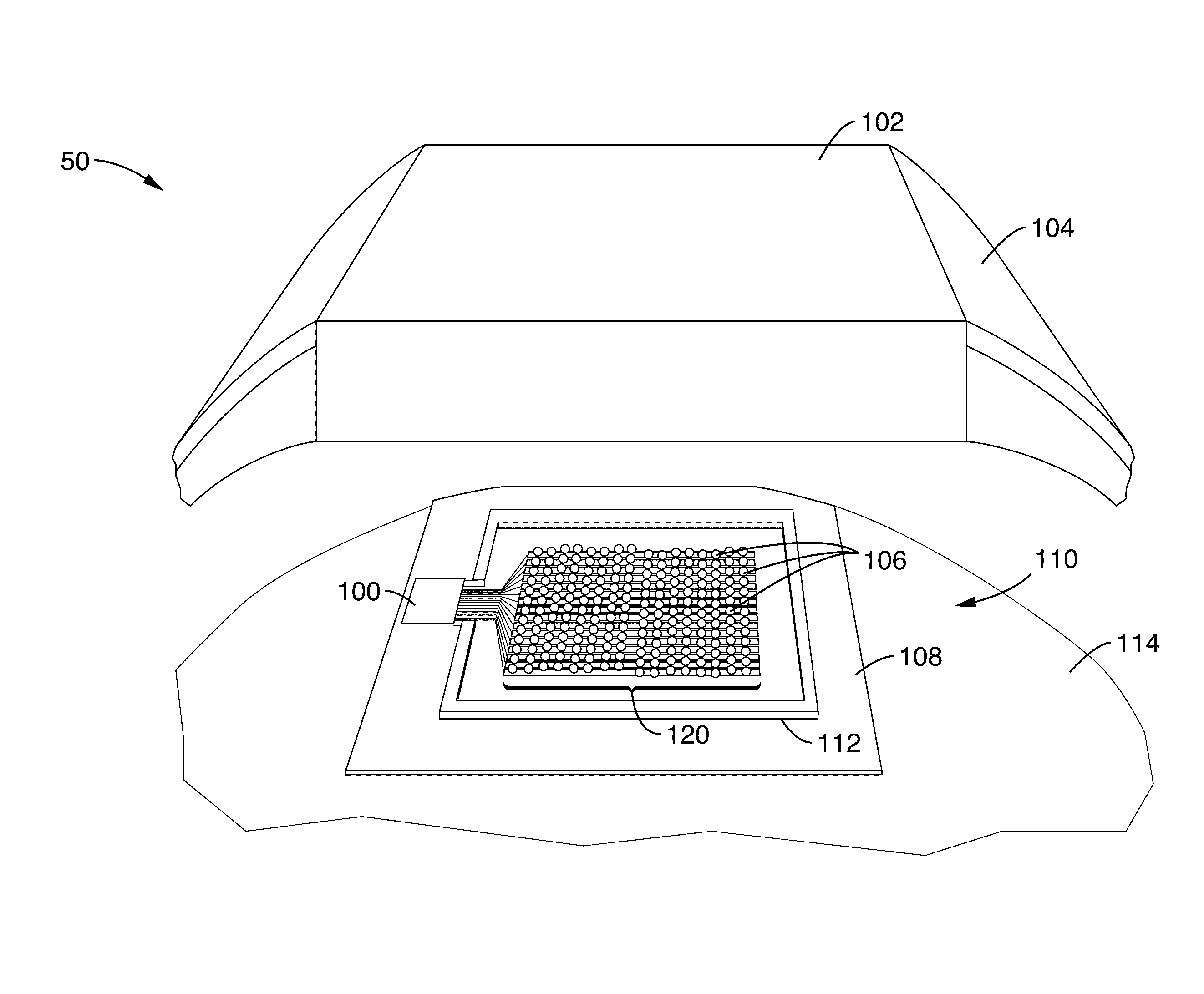
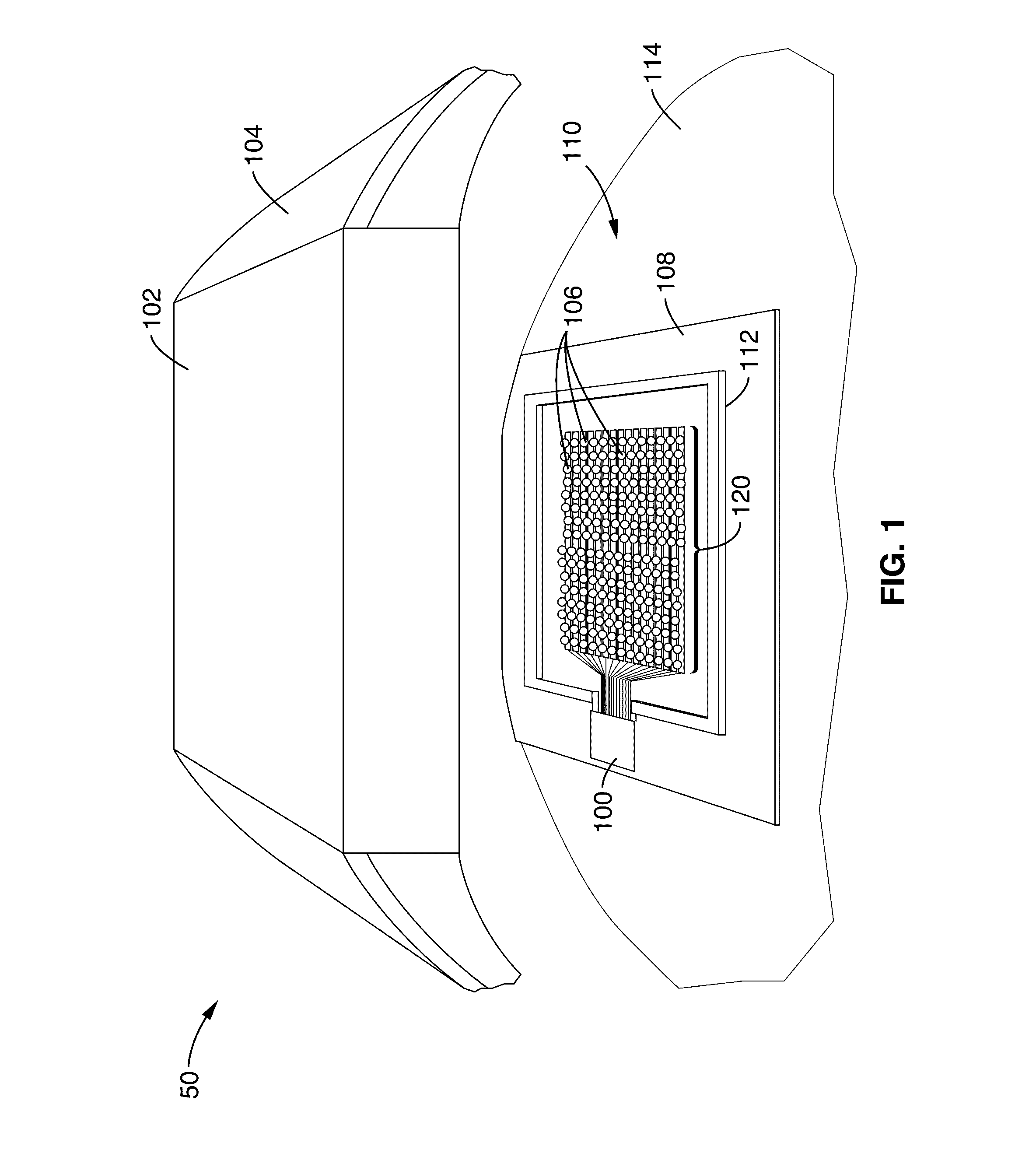
[0032]FIG. 1 shows a schematic system view of the implantable ECoG microsystem 50 in accordance with the present description. Microsystem 50 comprises an implant110 comprising an ECoG grid 120 for neural recordings and control circuitry 100 in the form of an IC configured to interface with and control ECoG grid 120. Implant is shown disposed on cortical surface 114 of the brain, with skull, skin, and intervening tissues between implant and external reader 102 are specifically not shown in FIG. 1 for clarity.

[0033]ECoG grid 120 comprises micro-fabricated array of electrodes 106 disposed on a flexible substrate 108, each electrode having sub-mm resolution and configured to acquire and measure signals associated with brain activity.

[0034]In a preferred embodiment, entire grid 120 is less than 10 μm thick and sufficiently flexible to conform to the highly folded cortical surface. In one exemplary configuration, the ECoG grid 120 comprises a 4 mm×4 mm, 64-channel array (e.g. 8×8 pattern ...


PUM


Abstract

A minimally invasive, wireless ECoG microsystem is provided for chronic and stable neural recording. Wireless powering and readout are combined with a dual rectification power management circuitry to simultaneously power to and transmit a continuous stream of data from an implant with a micro ECoG array and an external reader. Area and power reduction techniques in the baseband and wireless subsystem result in over 10×IC area reduction with a simultaneous 3× improvement in power efficiency, enabling a minimally invasive platform for 64-channel recording. The low power consumption of the IC, together with the antenna integration strategy, enables remote powering at 3× below established safety limits, while the small size and flexibility of the implant minimizes the foreign body response.

Description

CROSS-REFERENCE TO RELATED APPLICATIONS[0001]This application is a 35 U.S.C. §111(a) continuation of PCT international application number PCT / US2015 / 014905 filed on Feb. 6, 2015, incorporated herein by reference in its entirety, which claims priority to, and the benefit of, U.S. provisional patent application Ser. No. 61 / 937,434 filed on Feb. 7, 2014, incorporated herein by reference in its entirety. Priority is claimed to each of the foregoing applications.[0002]The above-referenced PCT international application was published as PCT International Publication No. WO 2015 / 120324 on Aug. 13, 2015, which publication is incorporated herein by reference in its entirety.STATEMENT REGARDING FEDERALLY SPONSORED RESEARCH OR DEVELOPMENT[0003]Not ApplicableINCORPORATION-BY-REFERENCE OF COMPUTER PROGRAM APPENDIX[0004]Not ApplicableNOTICE OF MATERIAL SUBJECT TO COPYRIGHT PROTECTION[0005]A portion of the material in this patent document is subject to copyright protection under the copyright laws ...

Claims


Application Information

Patent Timeline
IPC IPC(8): G06F3/01A61B5/04
CPCA61B5/04001G06F3/015A61B5/6868A61B2562/046A61B5/24A61B5/374A61B5/291
Inventor MULLER, RIKKYLEDOCHOWITSCH, PETERLE, HANH-PHUCGAMBINI, SIMONEMAHARBIZ, MICHELRABAEY, JAN
Owner RGT UNIV OF CALIFORNIA
Why Eureka
Try Eureka