

Laminated multilayer membranes, separators, batteries, and methods
- Summary
- Abstract
- Description
- Claims
- Application Information
AI Technical Summary
Benefits of technology
Problems solved by technology
Method used
Image

Examples
examples
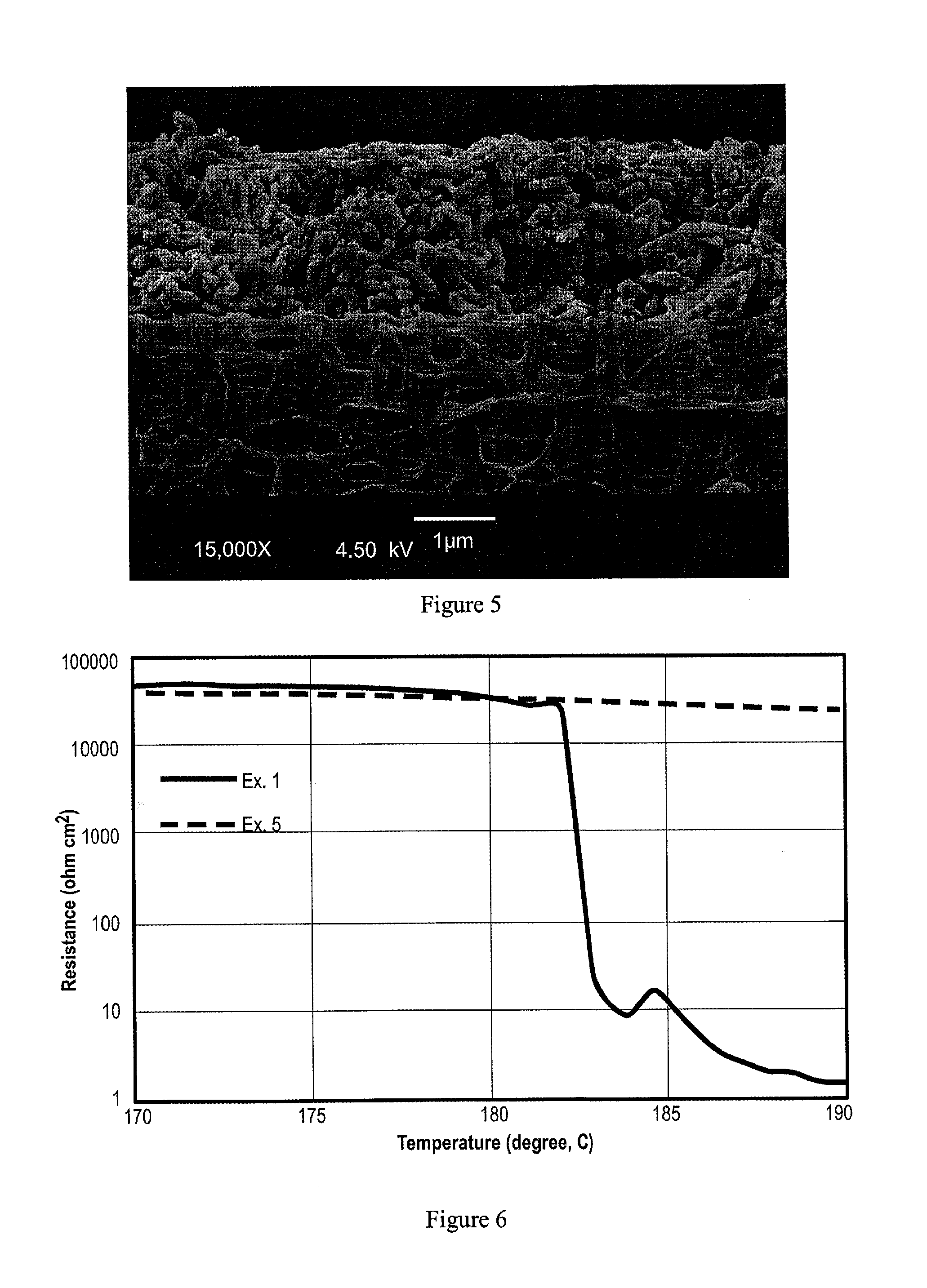
[0041]In the following Table, separator membrane property data is listed for battery separator membranes produced using the foregoing described process. Table 1 lists separator property and performance data on Inventive Example 1, Example 2, Example 3 (all three PE / PP / PE trilayer separator membranes made according to the processes described herein) together with Comparative Example CE 1, and Comparative Example CE 2.
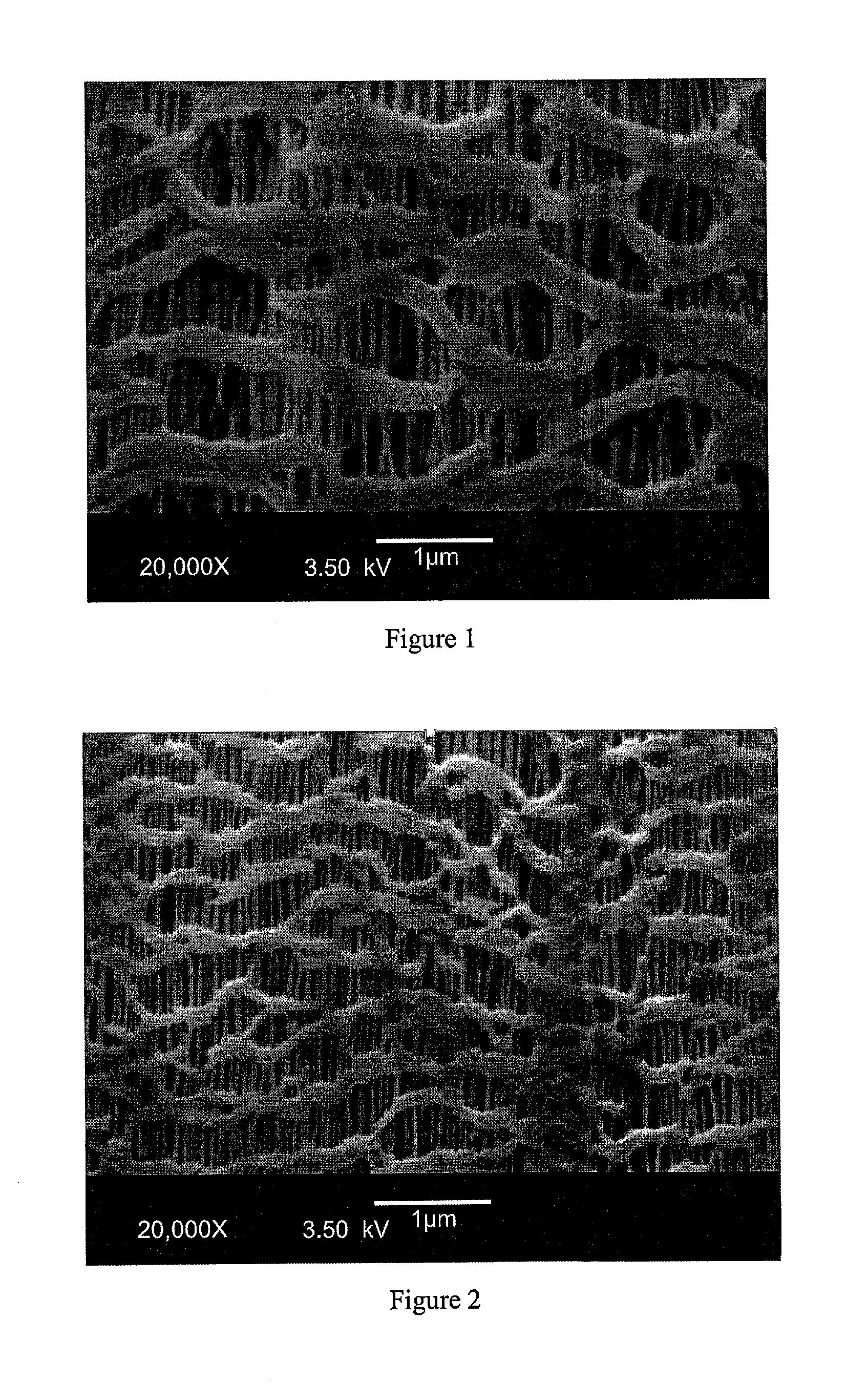
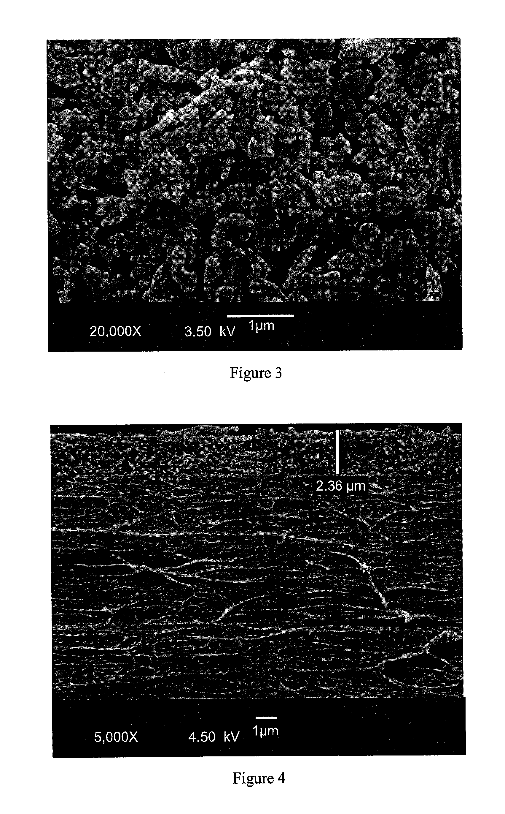
[0042]Example 1 is a PE1 / PP1 / PE1 laminated trilayer membrane with a thickness of 14.1 μm that includes a homopolymer polyethylene type 1, which is designated as PE1 and a homopolymer polypropylene type 1 which is designated as PP1. All three of Examples 1-3 are made according to the following process: the laminated trilayer nonporous precursor (having the general PE / PP / PE format) was formed, and the precursor was annealed. Then, the laminated precursor was uniaxially stretched in the machine direction only. Subsequently, the porous membrane was heat set, de-plied, and sl...
PUM
| Property | Measurement | Unit |
|---|---|---|
| Temperature | aaaaa | aaaaa |
| Temperature | aaaaa | aaaaa |
| Pore size | aaaaa | aaaaa |
Abstract
Description
Claims
Application Information