System and method for local three dimensional volume reconstruction using a standard fluoroscope

a fluoroscope and volume reconstruction technology, applied in the field of system, apparatus, and method of navigation and position confirmation for surgical procedures, can solve the problems of difficult resolving of small soft tissue objects of interest such as lesions in fluoroscopic images, high cost of mri system or ct-based imaging system, and tedious procedures, so as to improve the quality of three dimensional reconstruction, increase the accuracy of camera pose, and increase the effect of accuracy

Active Publication Date: 2017-02-09
TYCO HEALTHCARE GRP LP
View PDF8 Cites 22 Cited by
  • Summary
  • Abstract
  • Description
  • Claims
  • Application Information

AI Technical Summary

Benefits of technology

[0015]Additionally, or alternatively, the pose may be determined using an external measurement device and a single marker or a catheter tip. Specifically, in some cases, the fluoroscope (or C-arm) may jitter during rotation, in which case some stabilization is needed. Unfortunately, due to filtering, the angle measurement device may still report smooth angles throughout the video, ignoring the high-frequencies which are present in the actual camera poses. In this case, a single two dimensional marker can be tracked throughout the video and used to stabilize the camera poses, or to increase their accuracy at the area ...

Problems solved by technology

An MRI system or CT-based imaging system is extremely costly, and in many cases not available in the same location as the location where a navigation plan is generated or where a navigation procedure is carried out.
However, although standard fluoroscopic images display highly dense objects such as metal tools and bones as well as large soft-tissue objects such as the heart, the fluoroscopic images have difficulty resolving small soft-tissue objects of interest such as lesions.
This is a tedious procedure as it requires several full CT scans, a dedicated CT room and blind navigation ...

Method used


Image

  • System and method for local three dimensional volume reconstruction using a standard fluoroscope
  • System and method for local three dimensional volume reconstruction using a standard fluoroscope
  • System and method for local three dimensional volume reconstruction using a standard fluoroscope

Examples


Embodiment Construction

[0041]The present disclosure is directed to a system and method for constructing local three dimensional volumetric data, in which small soft-tissue objects are visible, from a video stream captured by a standard fluoroscopic imaging device available in most procedure rooms. The constructed fluoroscopic-based local three dimensional volumetric data may be used for guidance, navigation planning, improved navigation accuracy, navigation confirmation, and treatment confirmation.

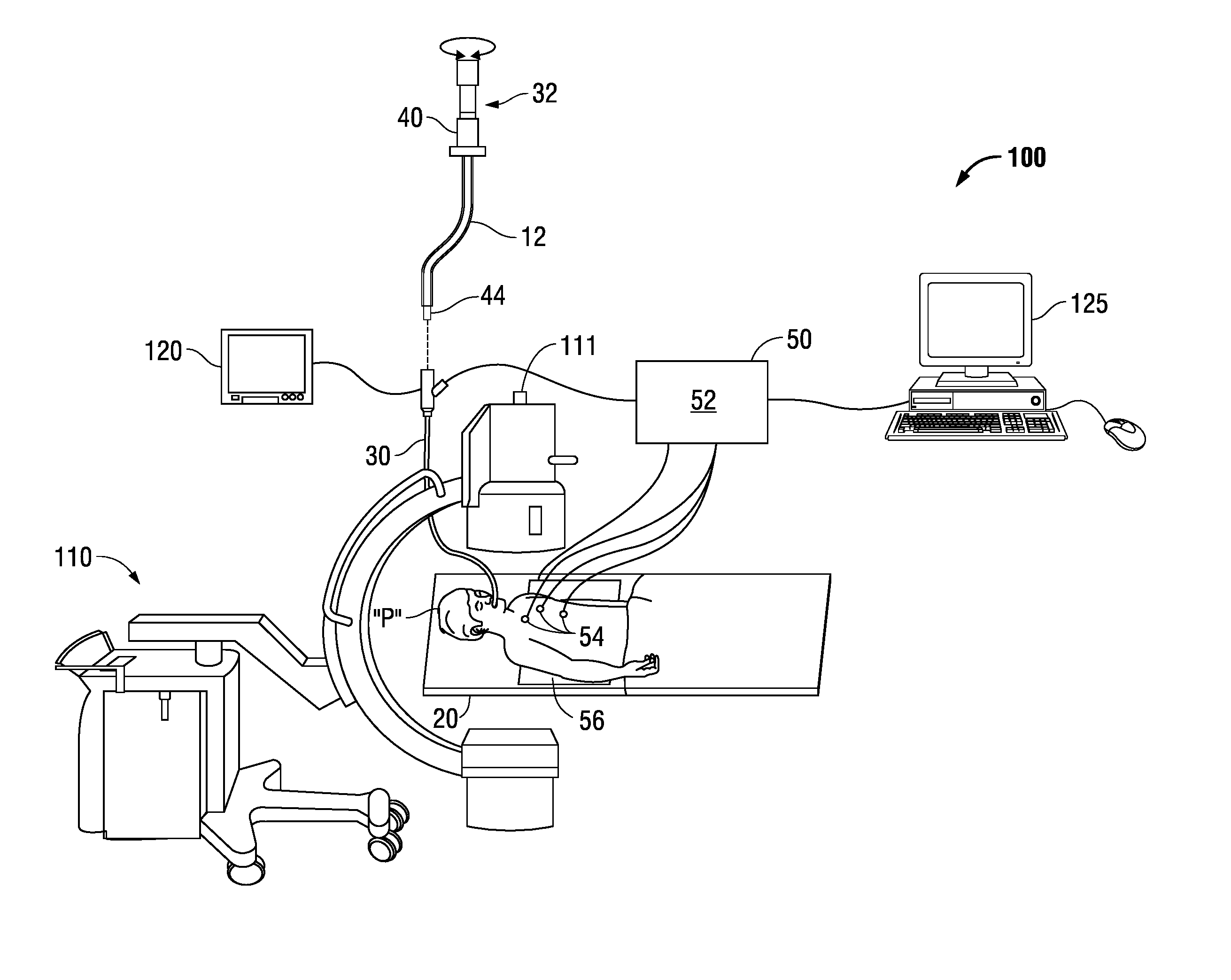
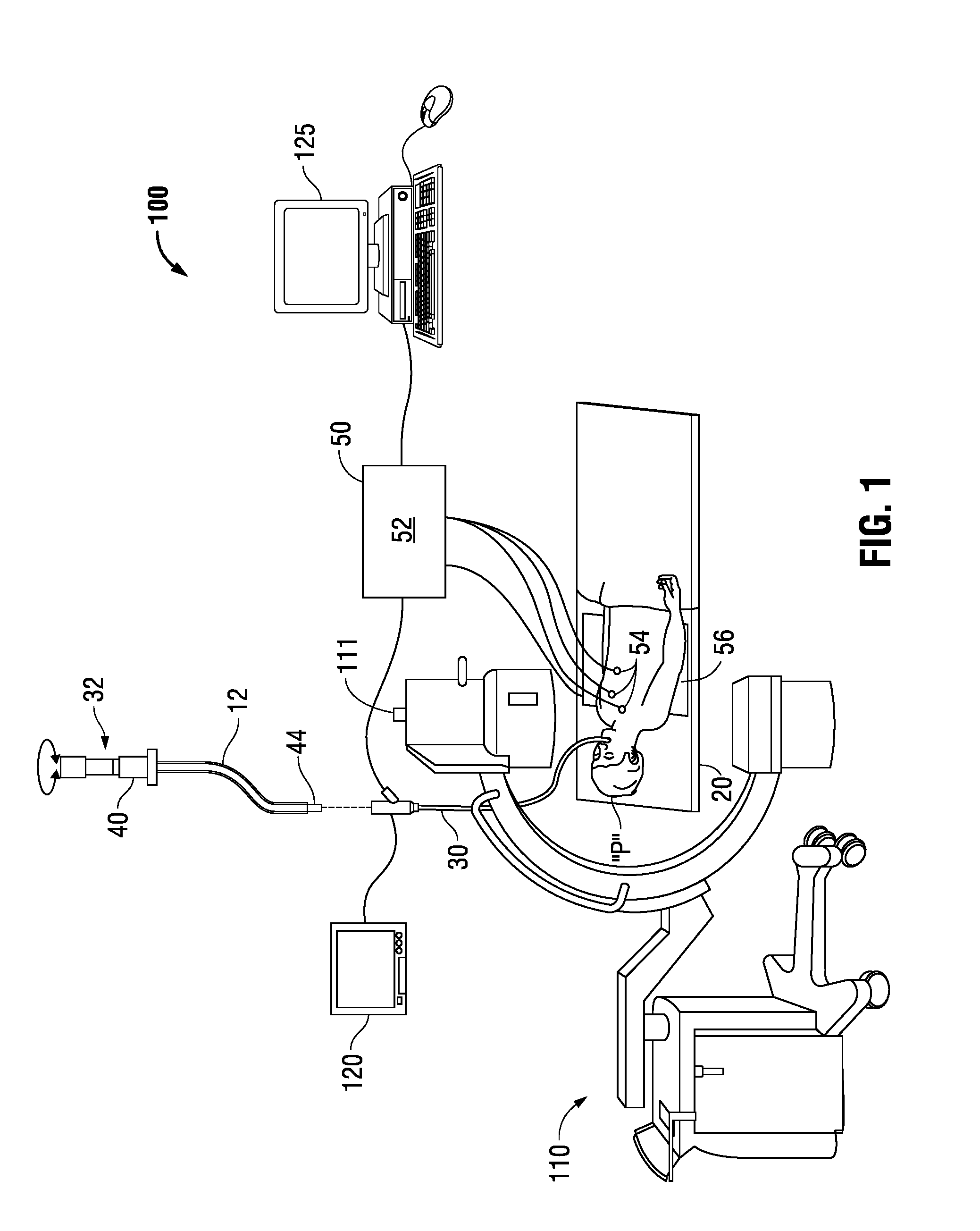
[0042]FIG. 1 depicts an Electromagnetic Navigation (EMN) system 100 configured for reviewing CT image data to identify one or more targets, planning a pathway to an identified target (planning phase), navigating an extended working channel (EWC) 12 of a catheter assembly to a target (navigation phase) via a user interface, and confirming placement of the EWC 12 relative to the target. One such EMN system is the ELECTROMAGNETIC NAVIGATION BRONCHOSCOPY® system currently sold by Medtronic PLC. The target may be tis...


PUM


Abstract

A system and method for constructing fluoroscopic-based three dimensional volumetric data from two dimensional fluoroscopic images including a computing device configured to facilitate navigation of a medical device to a target area within a patient and a fluoroscopic imaging device configured to acquire a fluoroscopic video of the target area about a plurality of angles relative to the target area. The computing device is configured to determine a pose of the fluoroscopic imaging device for each frame of the fluoroscopic video and to construct fluoroscopic-based three dimensional volumetric data of the target area in which soft tissue objects are visible using a fast iterative three dimensional construction algorithm.

Description

CROSS-REFERENCE TO RELATED APPLICATIONS[0001]This application claims priority to U.S. Provisional Application Ser. No. 62 / 201,750, filed on Aug. 6, 2015, the entire contents of which are incorporated by reference herein.BACKGROUNDTechnical Field[0002]The present disclosure relates to a system, apparatus, and method of navigation and position confirmation for surgical procedures. More particularly, the present disclosure relates to a system and method for constructing a fluoroscopic-based three dimensional volume from two dimensional fluoroscopic images captured using a standard fluoroscopic imaging device.Description of Related Art[0003]There are several commonly applied methods for treating various maladies affecting organs including the liver, brain, heart, lung and kidney. Often, one or more imaging modalities, such as magnetic resonance imaging, ultrasound imaging, computed tomography (CT), as well as others are employed by clinicians to identify areas of interest within a patie...

Claims


Application Information

Patent Timeline
IPC IPC(8): A61B6/00A61B5/107G06T7/60A61B90/00G06T7/00A61B34/20A61B5/00
CPCA61B6/487G06T2210/22A61B6/5205A61B6/4441A61B6/4405A61B6/5264A61B5/1073A61B5/6852A61B90/39G06T7/0012G06T7/602G06T7/0081G06T7/0024A61B2090/3966A61B2034/2051G06T2207/10121A61B34/20G06T17/10G06T2210/41A61B6/032A61B6/12A61B6/5235A61B90/00G06T7/30G06T7/11G06T7/62G06T11/006G06T2211/424A61B2090/376A61B2034/105A61B90/36A61B2034/2048A61B2090/367A61B6/025A61B6/547
Inventor WEINGARTEN, OREN P.BARAK, RON
Owner TYCO HEALTHCARE GRP LP
Why Eureka
Try Eureka