Method for recovering heat from internal combustion engines and for converting the recovered heat into mechanical energy

a technology of internal combustion engine and heat recovery, which is applied in the direction of internal combustion piston engine, steam engine plant, engine components, etc., can solve the problems of large variation in the useable waste heat of the internal combustion engine, unsteady heat flow, and inability to realize technology in practice, so as to reduce the heat loss to the surrounding environment

Inactive Publication Date: 2017-03-23
FRAUNHOFER GESELLSCHAFT ZUR FOERDERUNG DER ANGEWANDTEN FORSCHUNG EV
View PDF12 Cites 24 Cited by
  • Summary
  • Abstract
  • Description
  • Claims
  • Application Information

AI Technical Summary

Benefits of technology

[0027]While the heat accumulator fluid in the secondary circuit can basically also be heated by means of the at least one first heat exchanger which in this case comprises, for example, three heat exchange lines (such as firstly for the exhaust gas flow and secondly for the primary circuit and the secondary circuit, which is separated therefrom, of the heat accumulator fluid), the heat accumulator fluid in the secondary circuit—as indicated above—can be heated in a preferred embodiment by means of at least one second heat exchanger which is operated in particular by the residual heat of the combustion engine after the waste heat of the latter has been supplied by means of the at least one first heat exchanger to the heat accumulator fluid guided in the primary circuit. In this manner, the greatest possible quantity of heat can be extracted from the waste heat flow from the combustion engine without considerable losses occurring as per the conventional flow evaporators according to the prior art. This is noticeable positively with regard to optimum efficiency especially at relatively low exhaust gas temperatures, as are frequently present specifically in the case of combustion engines of motor vehicles.
[0029]In an advantageous embodiment, it can be provided in this connection that the condenser is supplied with a cooling medium, in particular from the combustion engine, wherein the cooling medium is heated as required, in particular during heating-up phases of the combustion engine, by the heat accumulator fluid. The removal of heat in the condenser can take place, for example, via the cooling circuit of the combustion engine or via other suitable cooling circuits of the motor vehicle or else directly into the ambient air. As soon as the condenser is integrated in the cooling circuit of the combustion engine and is supplied with the cooling medium of the combustion engine, in particular the cold starting behaviour of the combustion engine can consequently be improved and its hot running phase shortened by the cooling medium being preheated by the (residual) heat of the heat accumulator medium which is stored in the heat accumulator and is guided in the secondary circuit. The heating-up phases of the combustion engine can therefore be effectively shortened for as long as (residual) heat is still available in the heat accumulator.
[0031]In a further advantageous embodiment of the method according to the invention, it can be provided that the condensed heat accumulator fluid in the secondary circuit downstream of the condenser is temporarily stored in a buffer container from which said heat accumulator fluid is recirculated into the heat accumulator by means of the secondary pump. In respect of the device, for this purpose, the secondary circuit can have a buffer container, which is arranged downstream of the condenser and more expediently upstream of the preferably provided second heat exchanger, for the heat accumulator fluid. It is thereby possible to temporarily store the heat accumulator fluid, which is guided in the secondary circuit, downstream of the condenser and to recirculate said heat accumulator fluid in the heat accumulator depending on the temporarily available waste heat flow from the combustion engine and the thermodynamic state of the heat accumulator fluid in the heat accumulator.
[0039]In this manner, a (local) superheating of the heat accumulator fluid and of the components of its primary and secondary circuit can be reliably prevented by the waste heat flow or residual heat flow from the combustion engine being guided past the first and / or second heat exchanger.
[0047]The first heat exchanger and / or the second heat exchanger and optionally the third heat exchanger can furthermore expediently be fed by an exhaust gas flow from the combustion engine. An exhaust pipe guiding the exhaust gas flow should expediently be thermally insulated here, which, of course, also applies to the other components of the primary and secondary circuit of the heat accumulator medium and in particular to the heat accumulator itself which should be configured to be as adiabatic as possible and so as to have good heat insulation in order to minimize the heat losses to the surroundings. The heat accumulator can be, for example, of multi-walled design here and can have vacuum insulation and / or can be equipped with material which is capable of latent heat accumulation, and therefore the heat of the heat accumulator fluid can also be stored for one or more days without significant dissipation into the surroundings. Such thermal insulation of the heat accumulator therefore preferably has a multi-layered wall, in the intermediate space of which a negative pressure or vacuum prevails or an aerogel or a thermochemical storage medium is accommodated.

Problems solved by technology

However, firstly the high technical and structural outlay with regard to the evaporator and condenser used for the heat accumulator fluid in the cycle and, secondly, the complicated control and regulating technology have proven disadvantageous here, and therefore this technology has been unable to be realized in practice to date.
Furthermore, the technology known with regard to lorry engines is transferable at best to a limited extent to engines of passenger vehicles because, in contrast to lorries, passenger vehicles are generally operated with very different and frequently changing engine powers, and therefore the useable waste heat from the internal combustion engine greatly varies, wherein such unsteady heat flows are scarcely controllable by regulation technology for realizing the abovementioned Rankine cycles according to the prior art.
Also, the achievable efficiencies are very low in the case of a forced continuous operation of such a Rankine cycle.
A disadvantage firstly consists in that the thermal energy which can be stored by means of the steam accumulator has proven relatively small if the steam accumulator does not have a very large capacity which takes up the available loading compartment of the motor vehicle and, in addition, also causes a considerable additional weight in respect of the necessary thermal insulation of the steam accumulator, said additional weight resulting in turn in increased fuel consumption.

Method used


Image

  • Method for recovering heat from internal combustion engines and for converting the recovered heat into mechanical energy
  • Method for recovering heat from internal combustion engines and for converting the recovered heat into mechanical energy

Examples


Embodiment Construction

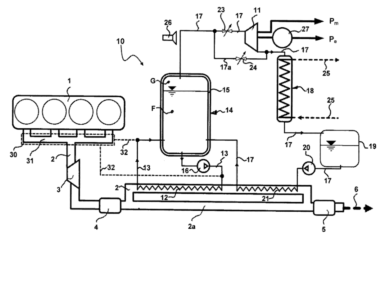
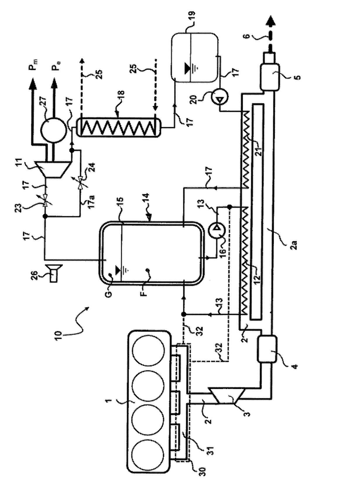
[0058]The drawing reproduces, in a schematic illustration, an internal combustion engine 1 of a motor vehicle (otherwise not shown), for example a passenger vehicle or a lorry, which has an exhaust pipe 2 in which the exhaust gas flow serving as the waste heat flow is removed from the internal combustion engine 1. The exhaust pipe 2 leads, for example, into a turbocharger 3 and into a catalytic convertor 4, which is arranged downstream of the latter, for the catalytic purification of the exhaust gas, and the exhaust gas flow downstream of the latter passes through an end silencer 5 and is removed into the surroundings via an exhaust 6.

[0059]A device, which is provided overall with the reference sign 10, for recovering heat from the internal combustion engine 1 and for converting the recovered heat into mechanical energy by means of an expansion machine 11 designed, for example, in the manner of a turbomachine or positive displacement machine, contains a heat accumulator fluid, for e...


PUM


Abstract

A method and a device for recovering heat from an engine and for converting the heat into mechanical energy using an expansion machine. A heat accumulator fluid is guided in a primary circuit by means of a primary pump and is firstly heated by the waste heat of the combustion engine by means of a heat exchanger, is transferred into a heat accumulator and recirculated to the first heat exchanger, and, secondly, the heat accumulator fluid is guided in a secondary circuit by said heat accumulator fluid being extracted in the vapor state from the heat accumulator and being supplied to the expansion machine, and being condensed by means of a condenser downstream thereof and being recirculated into the heat accumulator by means of a secondary pump. The primary circuit of the heat accumulator fluid is connected to the secondary circuit exclusively via the heat accumulator.

Description

[0001]This application is the national stage of PCT / EP2015 / 001012, filed May 18, 2015 and also claims Paris convention priority from DE 10 2014 007 214.2, filed May 19, 2014.BACKGROUND OF THE INVENTION[0002]The invention relates to a method for recovering heat from a combustion engine, in particular of a motor vehicle, and for converting the recovered heat into mechanical energy by means of an expansion machine, wherein a heat accumulator fluid which is guided in a primary circuit by means of at least one primary pump is heated by the waste heat of the combustion engine by means of at least one first heat exchanger, is transferred into a heat accumulator and recirculated to the at least one first heat exchanger, and wherein the heat accumulator fluid is furthermore guided in a secondary circuit by said heat accumulator fluid being extracted in the vapor state from the heat accumulator and being supplied to the expansion machine, and being condensed by means of a condenser downstream...

Claims


Application Information

Patent Timeline
Patent Type & Authority Applications(United States)
IPC IPC(8): F01K23/06F01K3/10F01K7/16F02B41/00F01K3/14F01K15/02F01K3/00F02G5/04
CPCF01K23/065F01K3/002F01K3/10F01K7/16F02B41/00F01K3/14F01K15/02F02G5/04F01K3/20F01K3/242Y02T10/12
Inventor KOLLMEIER, HANS-PETERKRALJEVIC, IVICAROHRPASSER, CHRISTIANSTRIEBICH, HELMUT
Owner FRAUNHOFER GESELLSCHAFT ZUR FOERDERUNG DER ANGEWANDTEN FORSCHUNG EV
Why Eureka
Try Eureka