Lidar sensor including an optical filter

a technology of optical filter and lidar sensor, which is applied in the field of lidar sensor, can solve the problems of limiting the sensitivity of lidar sensor, limiting the energy content of radiation component, and high optical quality of transmission filter, and achieves the effect of high sensitivity

Active Publication Date: 2017-03-23
ROBERT BOSCH GMBH
View PDF6 Cites 11 Cited by
  • Summary
  • Abstract
  • Description
  • Claims
  • Application Information

AI Technical Summary

Benefits of technology

[0008]Narrow-band reflection filters, i.e., filters that have a high reflectivity only at a special wavelength, may be manufactured relatively simply and cost-effectively. According to the present invention, the reflection filter is situated in the beam path in such a way that the incident light having useful wavelength λ0 is deflected to the receiver, while light having other wavelengths is allowed to pass through by the reflection filter and consequently does not reach the receiver. The transmission filter filters out light at wavelengths that differ more greatly from the useful wavelength. The transmission filter may be designed in such a way that it is sufficiently broadband to have a transmissivity of nearly 100% at useful wavelength λ0, so that the sensitivity of the LIDAR sensor is not impaired. The combined effect of the broadband transmission filter and the narrow-band reflection filter causes the light that is neither filtered out by the transmission filter nor deflected by the reflection filter to the receiver and consequently reaches the interior of the housing possibly resulting in heating, is essentially only made of wavelength components closely above and closely below the useful wavelength, and consequently the energy content of this radiation component is very small.
[0012]In a particularly advantageous specific embodiment, the reflection filter simultaneously forms a beam splitter, which allows a part of the light generated by the beam source to pass through, so that this light may be emitted into the locating range, and which deflects to the receiver a portion of the light reflected in the locating range and impinging again on the reflection filter. This has the advantage that the housing needs to have only a single window for the exit of the emitted beam and the entry of the reflected light. If the transmission filter is situated on or in this single window, the incidence of ambient light into the housing may be suppressed with the aid of a single transmission filter.

Problems solved by technology

A transmission filter having high optical quality is therefore relatively expensive.
Moreover, a more or less large portion of the light at useful wavelength λ0 is absorbed in the various layers of the filter, thus limiting the sensitivity of the LIDAR sensor, this limitation being intensified by increasing the narrow-bandedness of the filter.
The combined effect of the broadband transmission filter and the narrow-band reflection filter causes the light that is neither filtered out by the transmission filter nor deflected by the reflection filter to the receiver and consequently reaches the interior of the housing possibly resulting in heating, is essentially only made of wavelength components closely above and closely below the useful wavelength, and consequently the energy content of this radiation component is very small.

Method used


Image

  • Lidar sensor including an optical filter
  • Lidar sensor including an optical filter
  • Lidar sensor including an optical filter

Examples


Embodiment Construction

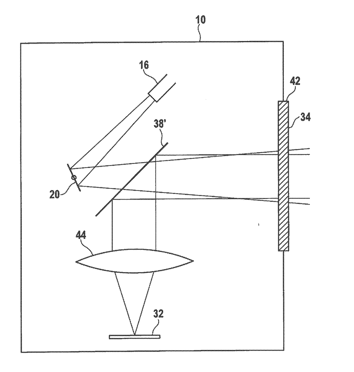
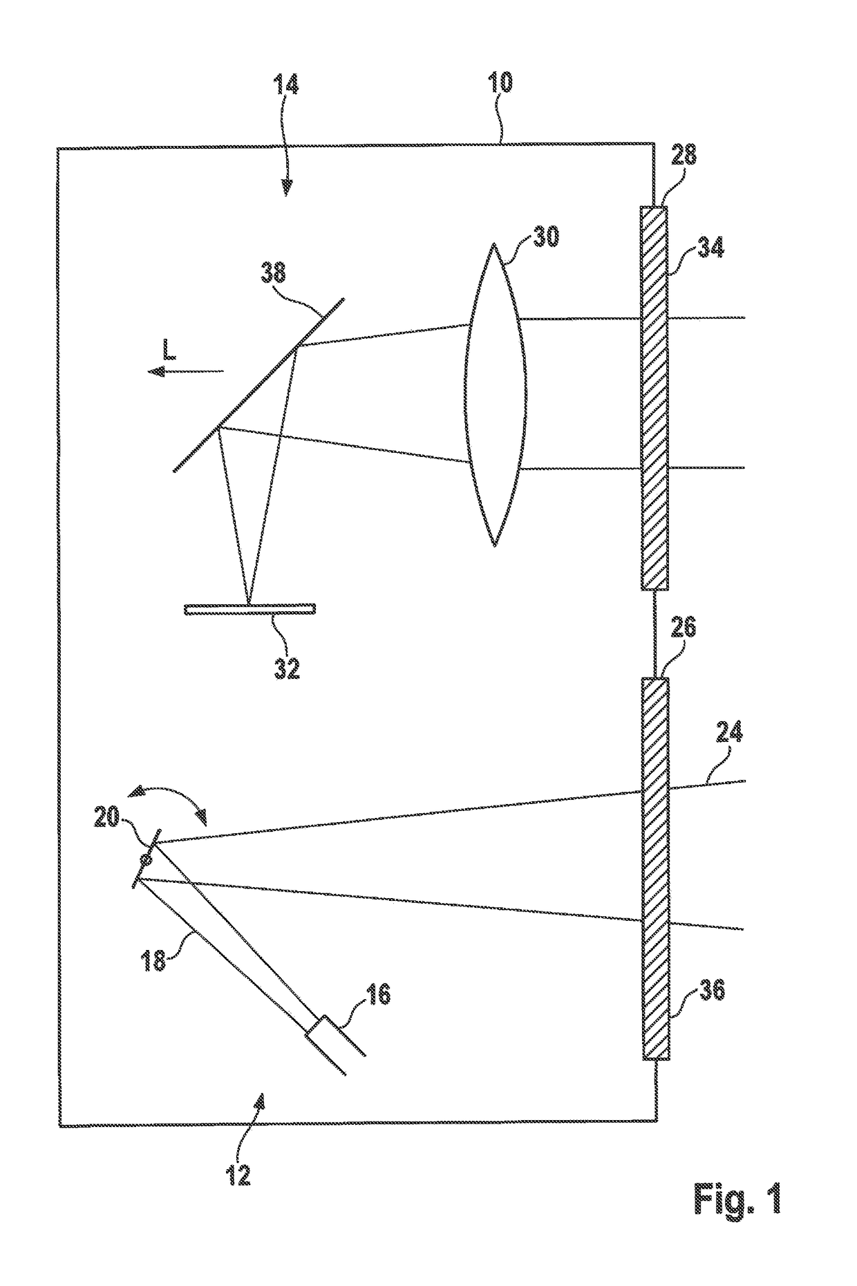
[0018]The LIDAR sensor shown in FIG. 1 has a housing 10, which accommodates a sending part 12 (below in FIG. 1), and a receiving part 14 (above) formed separately from the sending part.

[0019]Sending part 12 has a beam source 16, which is, for example, formed by a semiconductor laser, and emits a bundled beam 18 of laser light having a sharply defined useful wavelength λ0 onto a deflection mirror 20 which deviates in an oscillating manner. The light deflected on deflection mirror 20 exits housing 10 through an exit window 26 as scanning beam 24. Deflection mirror 20 deviates scanning beam 24 periodically in such a way that it scans a certain locating range.

[0020]The light reflected from objects in the locating range re-enters housing 10 through entrance window 28 and is focused by a lens 30 onto an optoelectronic receiver 32, which is formed, for example, by a CCD field. Based on the incidence location of the light on receiver 32, it is possible to determine the locating angle of the...


PUM


Abstract

A LIDAR sensor including an optical receiver and an optical filter situated in the beam path upstream from the receiver. The filter is formed by connecting a transmission filter and a reflection filter in series.

Description

CROSS REFERENCE[0001]The present application claims the benefit under 35 U.S.C. §119 of German Patent Application No. DE 102015217910.9 filed on Sep. 18, 2015, which is expressly incorporated herein by reference in its entirety.FIELD[0002]The present invention relates to a LIDAR sensor including an optical receiver and an optical filter situated in the beam path upstream from the receiver.BACKGROUND INFORMATION[0003]LIDAR sensors are used, for example, in driver assistance systems for motor vehicles for detecting the traffic environment. A beam source, typically a semiconductor laser, generates a bundled laser beam having a sharply defined useful wavelength λ0, which, for example, is deflected with the aid of an oscillating micro-mirror in such a way that it scans a certain angle range, or in the case of a two-dimensional deflection, a solid angle range. The scanned angle range or solid angle range is denoted as the locating range. If the laser beam strikes an object in the locating...

Claims


Application Information

Patent Timeline
Patent Type & Authority Applications(United States)
IPC IPC(8): G01S7/481G01S7/483G01S17/93G01S17/42G02B5/28G02B27/14G01S17/931
CPCG01S7/4811G02B5/285G01S7/483G01S17/936G01S17/42G02B27/141G01S7/4816G02B5/203G02B5/26G02B27/144G01S17/931
Inventor SCHWARZ, HANS-JOCHEN
Owner ROBERT BOSCH GMBH
Why Eureka
Try Eureka