Electronic Preamplifier System

a preamplifier and electronic technology, applied in the direction of amplifiers, low frequency amplifiers, amplifier input/output impedence modification, etc., can does not solve the problem of significant circuit sensitivity, and no preamplifier dedicated to cooperating with the microphon

Inactive Publication Date: 2017-03-30
RYBKA WOJCIECH
View PDF3 Cites 2 Cited by
  • Summary
  • Abstract
  • Description
  • Claims
  • Application Information

AI Technical Summary

Problems solved by technology

Although it is assumed that these devices are intended to serve as a low-frequency (LF) amplifier, their imperfections are often used in the process of creating sound.
This solution allows to obtain a higher quality signal by comparing the two differential output signals, but the end result still leaves much to be desired because of the sensitivity of the circuit to the quality of elements used, and the frequent use of inferior components on account of their price.
It does not solve the problem of significant sensitivity of the circuit to the quality of the components used.
In the light of these solutions it can be seen that there are no preamplifiers dedicated to cooperate with the microphones that provide high quality of the processed signals, even when using less expensive components.

Method used


Image

  • Electronic Preamplifier System
  • Electronic Preamplifier System
  • Electronic Preamplifier System

Examples


Embodiment Construction

[0055]Specific embodiments of the invention will now be described with reference to the accompanying drawings. This invention may, however, be embodied in many different forms and should not be construed as limited to the embodiments set forth herein; rather, these embodiments are provided so that this disclosure will be thorough and complete, and will fully convey the scope of the invention to those skilled in the art. The terminology used in the detailed description of the embodiments illustrated in the accompanying drawings is not intended to be limiting of the invention. In the drawings, like numbers refer to like elements.

[0056]The figures use the following indications:

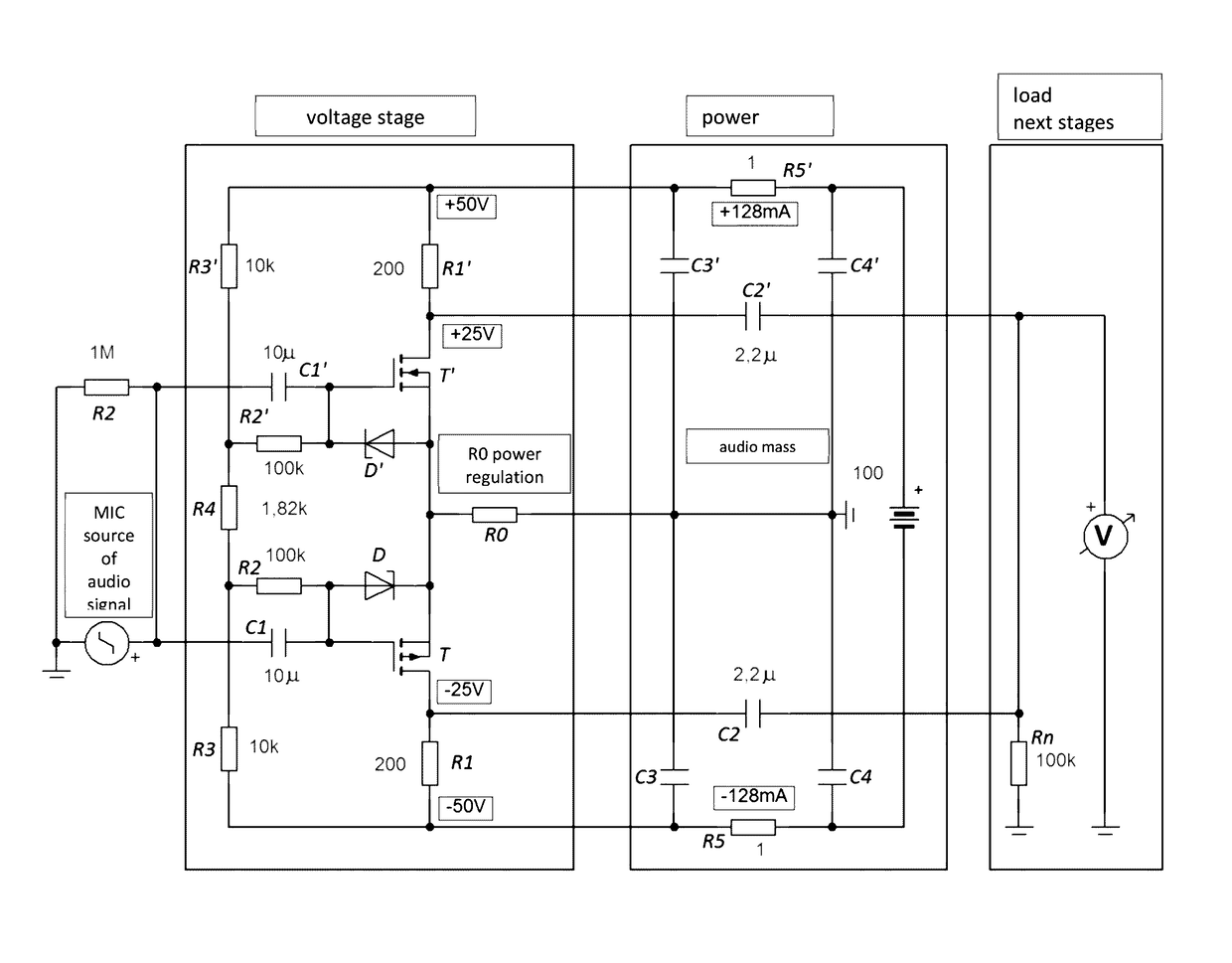
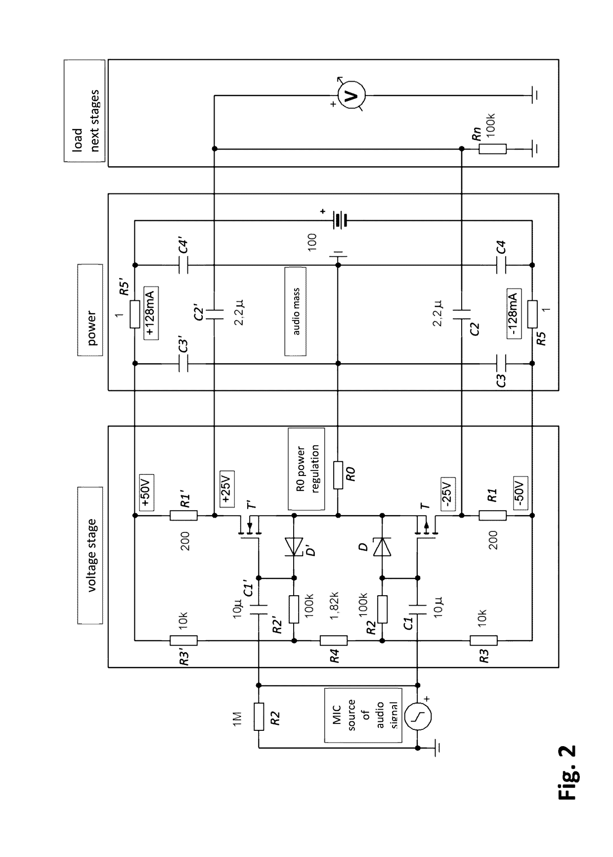
[0057]T—field transistor with the insulated gate IGFET MOSFET type with P-type enriched channel in the amplifier branch supplied with negative voltage, T′—the field transistor with IGFET gate MOSFET type with N-type enriched channel in the amplifier branch supplied with positive voltage; D—Zener diode in the bran...


PUM


Abstract

A graphene microphone preamplifier is a minimalist design working in class A with large quiescent current in a push-pull configuration, with automatic balancing of voltage imbalance.

Description

FIELD OF THE INVENTION[0001]The present invention relates to an electronic preamplifier system, especially a microphone preamplifier.BACKGROUND OF THE INVENTION[0002]A microphone preamplifier is a device used to increase the level of the microphone signal (typically by millivolts) to values close to the line level. Although it is assumed that these devices are intended to serve as a low-frequency (LF) amplifier, their imperfections are often used in the process of creating sound. They can also be part of a larger whole, i.e. a microphone track (stand-alone or being part of the mixer) containing additional signal processors like noise gates, filters, compressor, DeEsser, parametric EQ, limiter.[0003]In terms of the applied signal enhancer elements the following are distinguished:[0004]Tube preamplifiers[0005]Transistor preamplifiers[0006]Discrete[0007]Based on operational amplifiers[0008]Usually preamplifiers work in class A because of the required low level of harmonic distortion an...

Claims


Application Information

Patent Timeline
Patent Type & Authority Applications(United States)
IPC IPC(8): H03F3/185H04R3/04H03G3/30H03F1/56
CPCH03F3/185H04R3/04H03F3/68H03F2200/03H03G3/3005H03F3/3016H03F2203/30078H03F2203/30081H03F2203/30111H03F2203/30114H04R3/06
Inventor NAWROCKI, PIOTR
Owner RYBKA WOJCIECH
Why Eureka
Try Eureka