

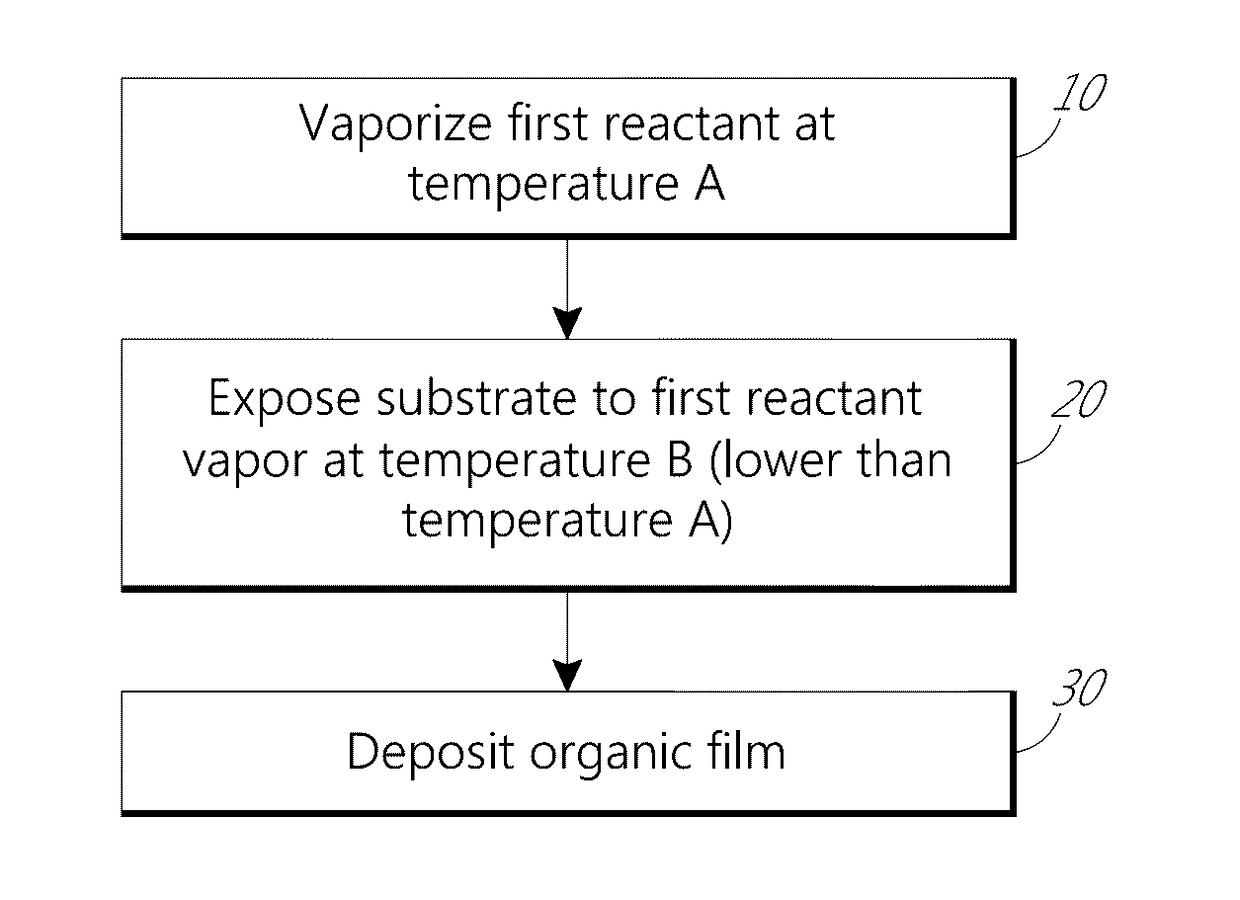
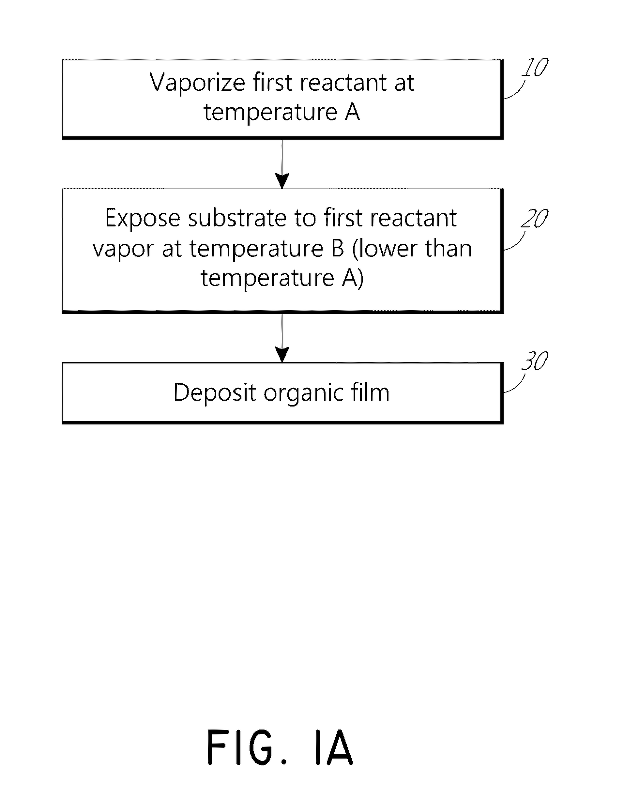
Vapor phase deposition of organic films
a technology of organic thin films and vapor phase, which is applied in the direction of liquid surface applicators, coatings, metal material coating processes, etc., can solve the problems of difficult control of uniform difficult to fill gaps of very small features, and difficult to control the formation of thin films on a substrate. uniform, the effect of reducing the aspect ratio of three-dimensional structures
- Summary
- Abstract
- Description
- Claims
- Application Information
AI Technical Summary
Benefits of technology
Problems solved by technology
Method used
Image

Examples
example 1
[0064]FIGS. 5A-5D show the results of experiments comparing similar sequential deposition processes using a negative temperature difference from the vaporizer to the substrate (FIGS. 5A & 5B) and using a positive temperature difference from the vaporizer to the substrate (FIGS. 5C & 5D). All experiments employed 300 mm wafers in a PULSAR 3000™ beta ALD tool supplied by ASM International, N.V. (Almere, The Netherlands). The negative temperature difference deposited a film at more than three times the growth rate, and produced a film with much higher thickness uniformity, compared to a process with a positive difference.
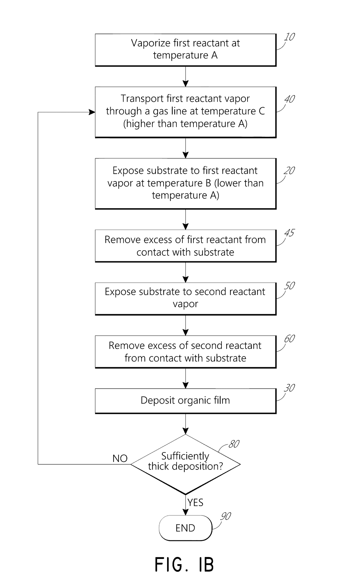
[0065]For the negative temperature difference experiment, PMDA and DAH were alternately and sequentially provided to the substrate in a sequential deposition process to deposit a polyimide film. The first reactant PMDA was vaporized at a temperature of 150° C., the PMDA gas line was maintained at 153° C., and the substrate was maintained at 127° C. The second reactant ...
example 2
[0067]In another negative temperature difference experiment conducted on wafers patterned with trenches, PMDA and DAH were reacted in a sequential process to deposit a polyimide film on a substrate with trench patterns. The trenches had variable pitches of 40 and 50 nm with 25-35 nm openings. The first reactant PMDA was vaporized at a temperature of 150° C., the PMDA gas line was maintained at 153° C., and the substrate was maintained at 127° C. The second reactant DAH was kept at 45° C. Line flows of 450 sccm were used, and pulse / purge lengths of 11 / 8.066 seconds and 4.68 / 9 seconds were used for PMDA and DAH, respectively. The resulting film was analyzed by tunneling electron microscopy (TEM). After 20 cycles, the TEM image showed that the film was thicker on the trench bottom areas, and thinner on the side walls of the trenches. The film thickness on a planar wafer grown using the same parameters was 7 nm, the film thickness on the bottom of some trenches was about 11 nm, and the ...
example 3
[0068]In another negative temperature difference experiment, PMDA and DAH were reacted in sequential deposition processes to deposit a polyimide films on substrates with trench patterns. Different time purge lengths were used. In one film, a purge length of 8.066 seconds was used for PMDA and 9.0 seconds for DAH, in another film a purge length of 15 seconds was used for each of PMDA and DAH, and in another film a purge length of 25 seconds was used for each of PMDA and DAH. The resulting films were analyzed by TEM. Purge length did seem to affect gap filling performance. However, shorter purges resulted in more planar film on top of the structures. Purge length can thus be used as a factor to tailor the final morphology of the film.
PUM
| Property | Measurement | Unit |
|---|---|---|
| temperature | aaaaa | aaaaa |
| temperature | aaaaa | aaaaa |
| temperature | aaaaa | aaaaa |
Abstract
Description
Claims
Application Information