Platinum thermocouple wire
- Summary
- Abstract
- Description
- Claims
- Application Information
AI Technical Summary
Benefits of technology
Problems solved by technology
Method used
Image
Examples
example 1
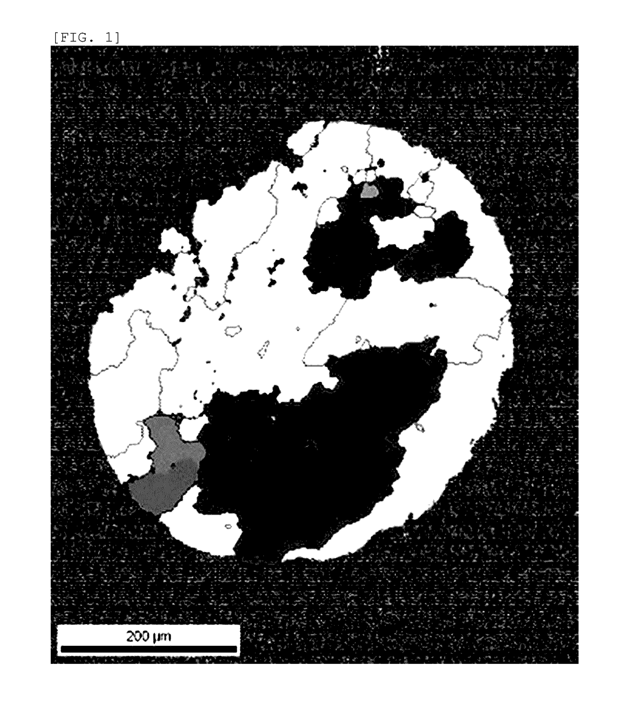
[0057]1000 g of high-purity platinum powder (platinum purity: 4 N, BET specific surface area: 0.195 m2 / g, porous powder, manufactured by FURUYA METAL Co., Ltd.) was prepared, this platinum powder was put into a vacuum chamber, the vacuum chamber was evacuated to 10 Pa or less, and then nitrogen gas (nitrogen gas purity: 4 N) was put into the vacuum chamber, thereby adsorbing the nitrogen gas to the surface of the platinum powder (including the surface in the pores). At this time, the nitrogen mass concentration as measured by a gas analyzer was 97 ppm. In addition, the oxygen mass concentration was 383 ppm. This platinum powder was sintered in vacuum by using a spark plasma sintering method to produce a platinum ingot (40 mmφ×40 mmh). The surface of this ingot was cleaned through machining or chemical treatment using aqua regia to remove the impurities. The nitrogen mass concentration of this platinum ingot was 80 ppm. In addition, the oxygen mass concentration was 87 ppm. Thereafte...
example 2
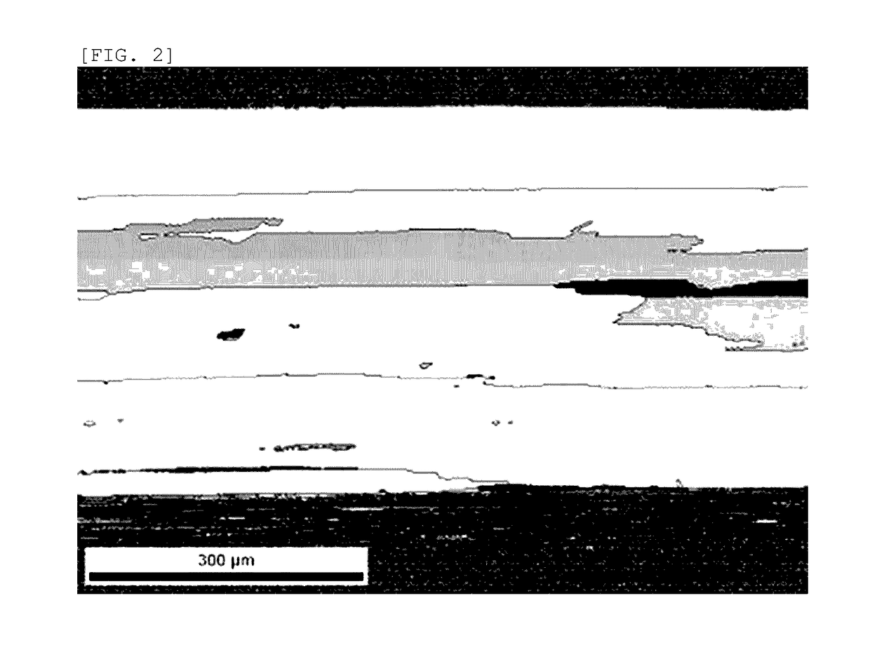
[0070]1000 g of high-purity platinum powder (platinum purity: 4 N, BET specific surface area: 0.195 m2 / g, porous powder, manufactured by FURUYA METAL Co., Ltd.) was prepared, this platinum powder was put into a vacuum chamber, the vacuum chamber was evacuated to 10 Pa or less, and then nitrogen gas (nitrogen gas purity: 4 N) was put into the vacuum chamber, thereby adsorbing the nitrogen gas to the surface of the platinum powder (including the surface in the pores). At this time, the nitrogen mass concentration as measured by a gas analyzer was 103 ppm. In addition, the oxygen mass concentration was 389 ppm. This platinum powder was sintered in vacuum by using a spark plasma sintering method to produce a platinum ingot (40 mmφ×40 mmh). The surface of this ingot was cleaned through machining or chemical treatment using aqua regia to remove the impurities. The nitrogen mass concentration of this platinum ingot was 84 ppm. In addition, the oxygen mass concentration was 73 ppm. Thereaft...
example 3
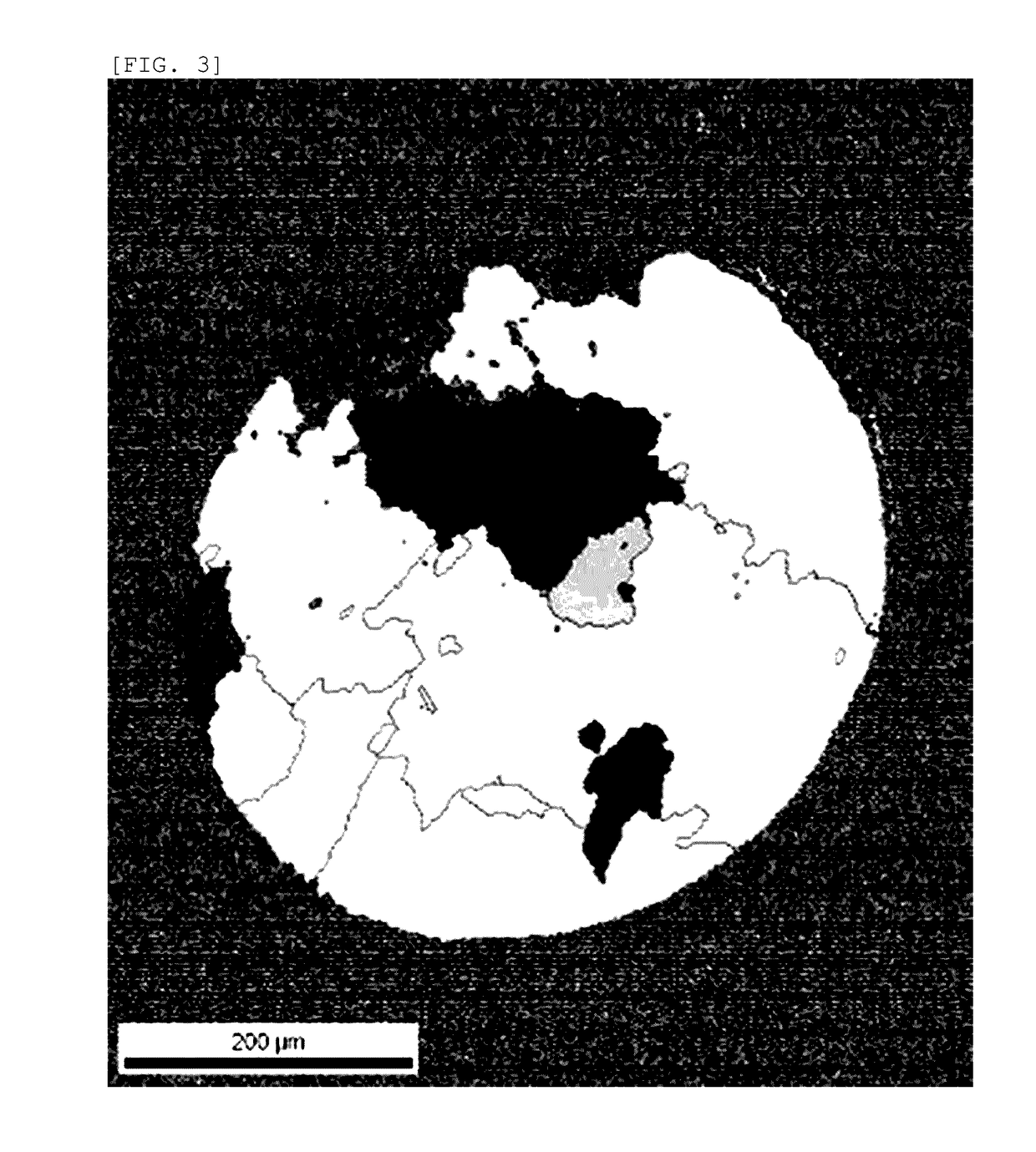
[0076]1000 g of high-purity platinum powder (platinum purity: 4 N, BET specific surface area: 0.195 m2 / g, porous powder, manufactured by FURUYA METAL Co., Ltd.) was prepared, this platinum powder was put into a vacuum chamber, the vacuum chamber was evacuated to 10 Pa or less, and then nitrogen gas (nitrogen gas purity: 4 N) was put into the vacuum chamber, thereby adsorbing the nitrogen gas to the surface of the platinum powder (including the surface in the pores). At this time, the nitrogen mass concentration as measured by a gas analyzer was 109 ppm. In addition, the oxygen mass concentration was 375 ppm. This platinum powder was sintered in vacuum by using a spark plasma sintering method to produce a platinum ingot (40 mmφ×40 mmh). The surface of this ingot was cleaned through machining or chemical treatment using aqua regia to remove the impurities. The nitrogen mass concentration of this platinum ingot was 84 ppm. In addition, the oxygen mass concentration was 64 ppm. Thereaft...
PUM
| Property | Measurement | Unit |
|---|---|---|
| Temperature | aaaaa | aaaaa |
| Fraction | aaaaa | aaaaa |
| Fraction | aaaaa | aaaaa |
Abstract
Description
Claims
Application Information
 - R&D
- Intellectual Property
- Life Sciences
- Materials
- Tech Scout
- Unparalleled Data Quality
- Higher Quality Content
- 60% Fewer Hallucinations
Browse by: Latest US Patents, China's latest patents, Technical Efficacy Thesaurus, Application Domain, Technology Topic, Popular Technical Reports.
© 2025 PatSnap. All rights reserved.Legal|Privacy policy|Modern Slavery Act Transparency Statement|Sitemap|About US| Contact US: help@patsnap.com


