Aspirator or pressurizer

Active Publication Date: 2017-04-27
MURATA MFG CO LTD
View PDF11 Cites 6 Cited by
  • Summary
  • Abstract
  • Description
  • Claims
  • Application Information

AI Technical Summary

Benefits of technology

[0006]In the nasal mucus aspirator described in Patent Document 1, since suctioning continues at constant suction pressure, the suction pressure of the nasal mucus aspirator needs to be set high to ensure reliable suctioning of the nasal mucus. However, this increases the power consumption of the nasal mucus aspirator during operation. Additionally, if the suction tube does not successfully hit the nasal mucus, a large amount of air may be suctioned all at once from the nasal c

Problems solved by technology

However, this increases the power consumption of the nasal mucus aspirator during operation.
Additionally, if the suction tube does not successfully hit the nasal mucus, a large amount of air may be suctioned all at once from the nasal cavity, and this may negatively affect the human body.
On the other hand, if the suction pressure of the nasal mucus aspira

Method used


Image

  • Aspirator or pressurizer
  • Aspirator or pressurizer
  • Aspirator or pressurizer

Examples


first embodiment

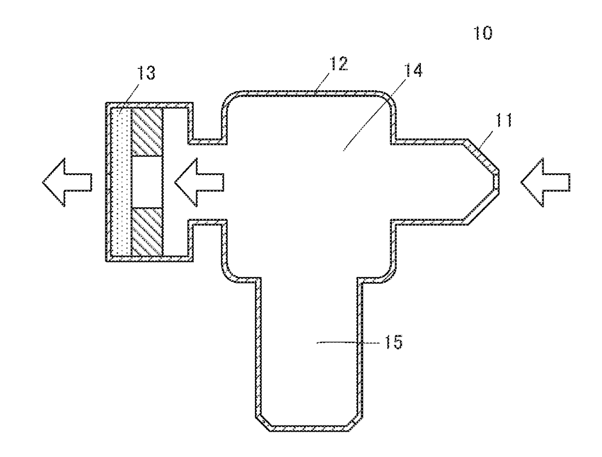
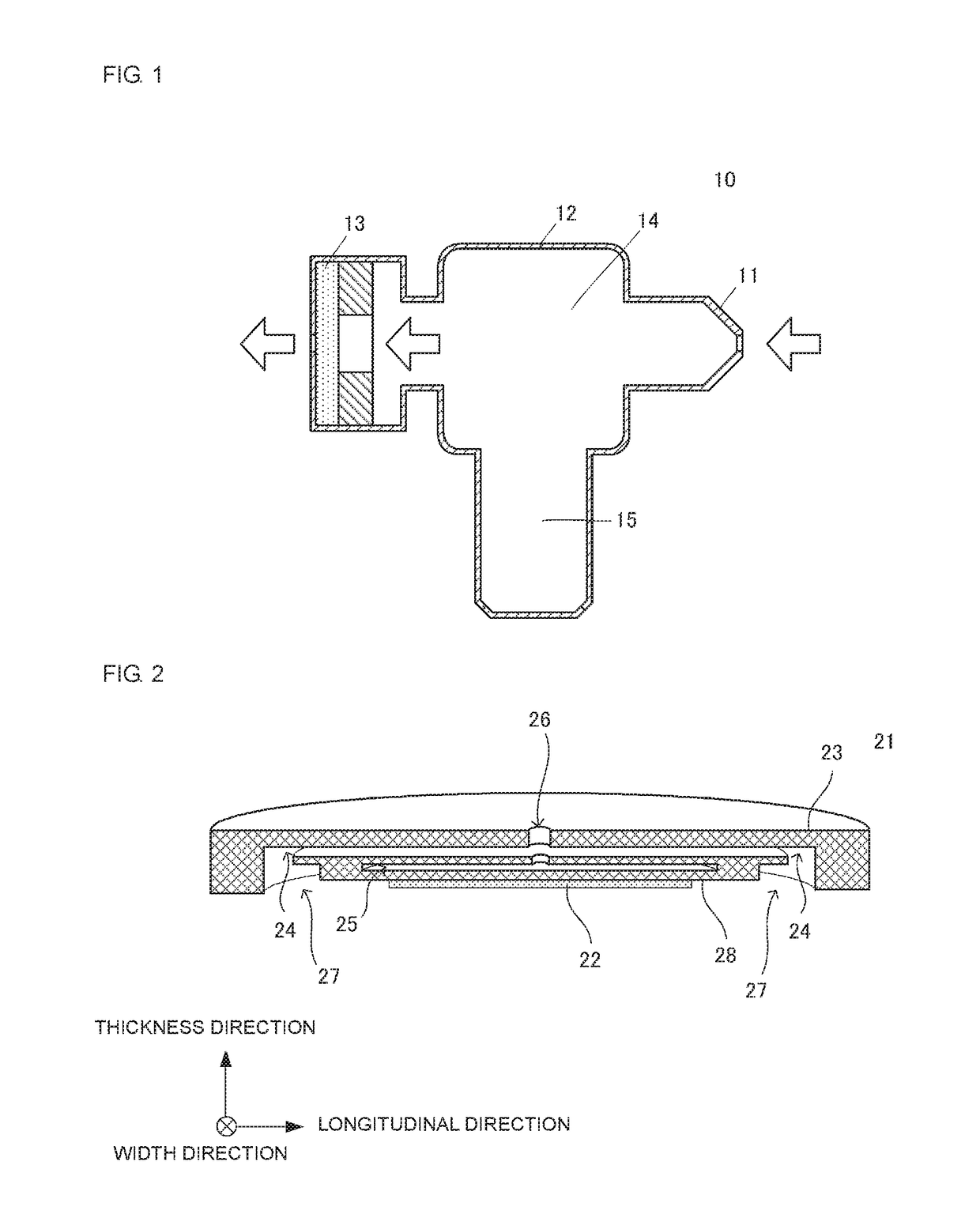
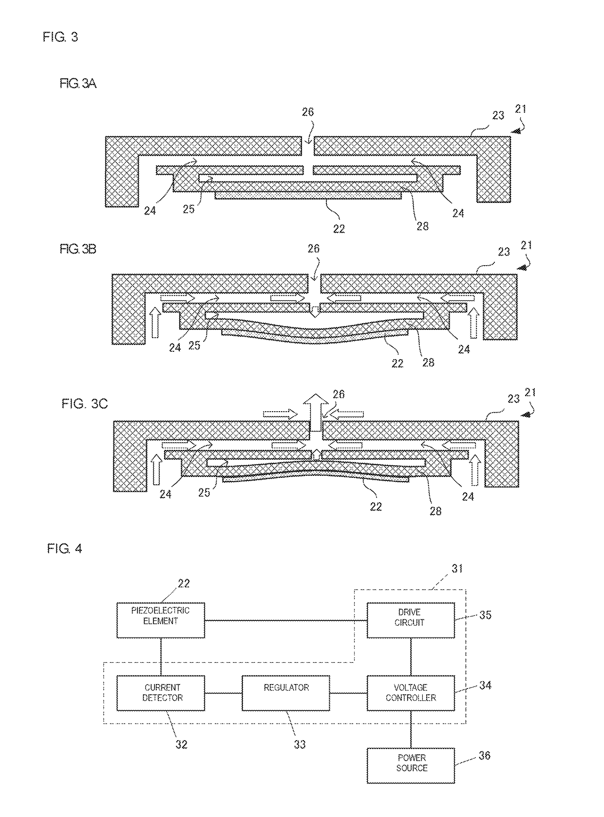
[0038]An aspirator 10 according to a first embodiment of the present disclosure will be described. The aspirator 10 is used to suction nasal mucus. FIG. 1 is a schematic cross-sectional view of the aspirator 10. The aspirator 10 includes a nozzle 11, a separator 12, and a piezoelectric drive unit 13 arranged in this order from front to rear. The aspirator 10 has a flow passage 14 that connects the front end of the nozzle 11 to the rear end of the piezoelectric drive unit 13. The separator 12 includes a storage unit 15 that branches off the flow passage 14. The piezoelectric drive unit 13 includes a piezoelectric pump 21 (see FIG. 2) and a circuit unit 31 (see FIG. 4) for driving the piezoelectric pump 21. The piezoelectric pump 21 corresponds to a pump of the present disclosure. The aspirator 10 includes an indicator (not shown) configured to display the state of the front end of the nozzle 11.

[0039]In the aspirator 10, the front end of the nozzle 11 is inserted into the nasal cavit...

second embodiment

[0060]An aspirator according to a second embodiment of the present disclosure will be described. FIG. 9 is a block diagram of a circuit unit 41 according to the second embodiment. The circuit unit 41 includes a current detector 42, a voltage detector 43, a phase comparator 44, a microcontroller (MCU) 45, and a resistor 46. The current detector 42 measures a current flowing through the piezoelectric element 22 by measuring a voltage across both ends of the resistor 46 whose resistance value is known. The resistor 46 is inserted in a voltage line that connects the piezoelectric element 22 to the drive circuit 35. The voltage detector 43 measures a drive voltage applied to the piezoelectric element 22. The phase comparator 44 outputs a phase difference θ between the current measured by the current detector 42 and the voltage measured by the voltage detector 43. The microcontroller 45 outputs a voltage having a predetermined pattern to the drive circuit 35 on the basis of the phase diff...

third embodiment

[0065]An aspirator according to a third embodiment of the present disclosure will be described. FIG. 11 is a block diagram of a circuit unit 51 according to the third embodiment. The circuit unit 51 includes a resonant frequency computing unit 57. The resonant frequency computing unit 57 calculates a resonant frequency f of the piezoelectric element 22 on the basis of the current measured by the current detector 32. The regulator 33 determines the state of the nozzle end on the basis of the resonant frequency f calculated by the resonant frequency computing unit 57.

[0066]The resonant frequency of the piezoelectric element 22 is a frequency at which the magnitude of the impedance of the piezoelectric element 22 is minimized, that is, a frequency at which the amplitude of the current flowing through the piezoelectric element 22 is maximized. The resonant frequency of the piezoelectric element 22 can be calculated by varying the drive frequency within a predetermined range, measuring t...


PUM


Abstract

An aspirator includes a pump, a detecting unit, and a control unit. The pump is driven by a piezoelectric element and has a suction portion and a discharge portion. The detecting unit includes a current detector and a regulator, and detects a closed state of the suction portion. The control unit includes the regulator and a voltage controller, and regulates an output voltage for the piezoelectric element in accordance with the closed state of the suction portion detected by the detecting unit.

Description

[0001]This application is a continuation of International Application no. PCT / JP2015 / 069851 filed on Jul. 10, 2015 which claims priority from Japanese patent application no. JP 2014-143125 filed on Jul. 11, 2014. The contents of these applications are incorporated herein by reference in their entireties.BACKGROUNDTechnical Field[0002]The present disclosure relates to an aspirator or pressurizer including a pump.[0003]Examples of conventional aspirators include a nasal mucus aspirator described in Patent Document 1. The nasal mucus aspirator includes a vacuum generator, a nasal mucus storage cylinder, a suction tube, and an actuator. The vacuum generator and the nasal mucus storage cylinder are coupled to each other by a tube. The nasal mucus storage cylinder is coupled to the suction tube for suctioning nasal mucus. The actuator is configured to start and stop suctioning of the nasal mucus. In this nasal mucus aspirator, when the suction tube is inserted into a nasal cavity and a bu...

Claims


Application Information

Patent Timeline
IPC IPC(8): A61G7/057A61M1/00
CPCA61G7/057A61M1/0066A61M2210/0618A61M2205/3334A61M2205/583A61M1/008A61M1/00A61M2205/3344A61M1/80A61M1/84
Inventor TANAKA, NOBUHIRA
Owner MURATA MFG CO LTD
Why Eureka
Try Eureka