Improvements in or relating to structured illumination microscopy utilising acousto-optic deflectors

a technology of acousto-optic deflectors and structured illumination, applied in the field of superresolution microscopy, can solve the problems of significant temporal and spatial dispersion, reduce efficiency and resolution, and the aods have not been widely adopted, so as to reduce the variation across the illumination area, reduce the distortion of the spatial profile of the beam, and increase the displacement range.

Inactive Publication Date: 2017-04-27
UNIVERSITY OF LEICESTER
View PDF0 Cites 2 Cited by
  • Summary
  • Abstract
  • Description
  • Claims
  • Application Information

AI Technical Summary

Benefits of technology

[0008]Use of a dynamically varied frequency for the acoustic compensation signal or the acoustic deflection signals increases the range of displacement that can be achieved using a particular beam steering arrangement whilst minimising distortion of the spatial profile of the beam or spatial displacement of the beam. Furthermore, dynamic modulation of the acoustic compensation signal can also provide control over the spatial intensity of illumination of the beam so as to reduce the variation across the illumination area as a whole. In a particular example, this can result in an increase in the effective scan angle of up to 4mrads compared to constant acoustic compensation frequency devices, thus increasing the illuminable area by around 15%.
[0009]The dynamic frequency variation may occur according to any suitable criteria. Preferably the dynamic frequency variation comprises modulation of the acoustic compensation signal frequency about a centre frequency or modulation of the acoustic deflection signals about a centre frequency or a centre frequency pattern. For a regular grid scanning pattern, the modulation of the acoustic deflection signals may be substantially sinusoidal or triangular. For a pattern with a static optimum modulation frequency of 100 MHz, variations of the order of, say, ±2 MHz (and in one preferred embodiment ±0.8 MHz) improve the overall compensation over a larger scan area. For a regular grid scanning pattern, the modulation of the acoustic compensation signal may be defined by an inverted and scaled intensity profile for a single grid line. The intensity profile may be an expected intensity profile. Alternatively, the intensity profile may be a measured intensity profile. In such cases, the measurements may be based on the preceding line or the present line in a preceding scan. The modulation may be adjusted during operation.

Problems solved by technology

AODs have not been widely adopted for use in multi-photon microscopy because they cause significant temporal and spatial dispersion of the femtosecond pulses required for multi-photon activation.
These effects reduce their efficiency and resolution unless they are properly compensated [12-18].
Nevertheless, even using these techniques, there is still a limit to the displacement achievable using AODs and in particular to the displacement achievable without adversely impacting on the spatial profile of the beam.
One way to combat the beam profile problem is to use large aperture AOMs and AODs but relatively small increases in the aperture size of such devices correlate to relatively large increases in their expense.
These effects can reduce the efficiency and resolution achievable.

Method used


Image

  • Improvements in or relating to structured illumination microscopy utilising acousto-optic deflectors
  • Improvements in or relating to structured illumination microscopy utilising acousto-optic deflectors
  • Improvements in or relating to structured illumination microscopy utilising acousto-optic deflectors

Examples


Embodiment Construction

[0022]In order that the invention may be more clearly understood an embodiment / embodiments thereof will now be described, by way of example only, with reference to the accompanying drawings, of which:

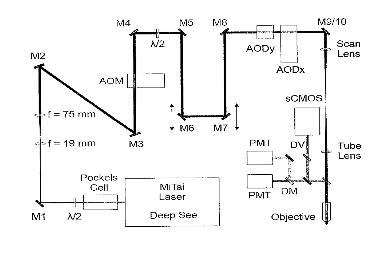
[0023]FIG. 1 shows a schematic illustration of an apparatus for structured illumination microscopy (SIM) according to the present invention;

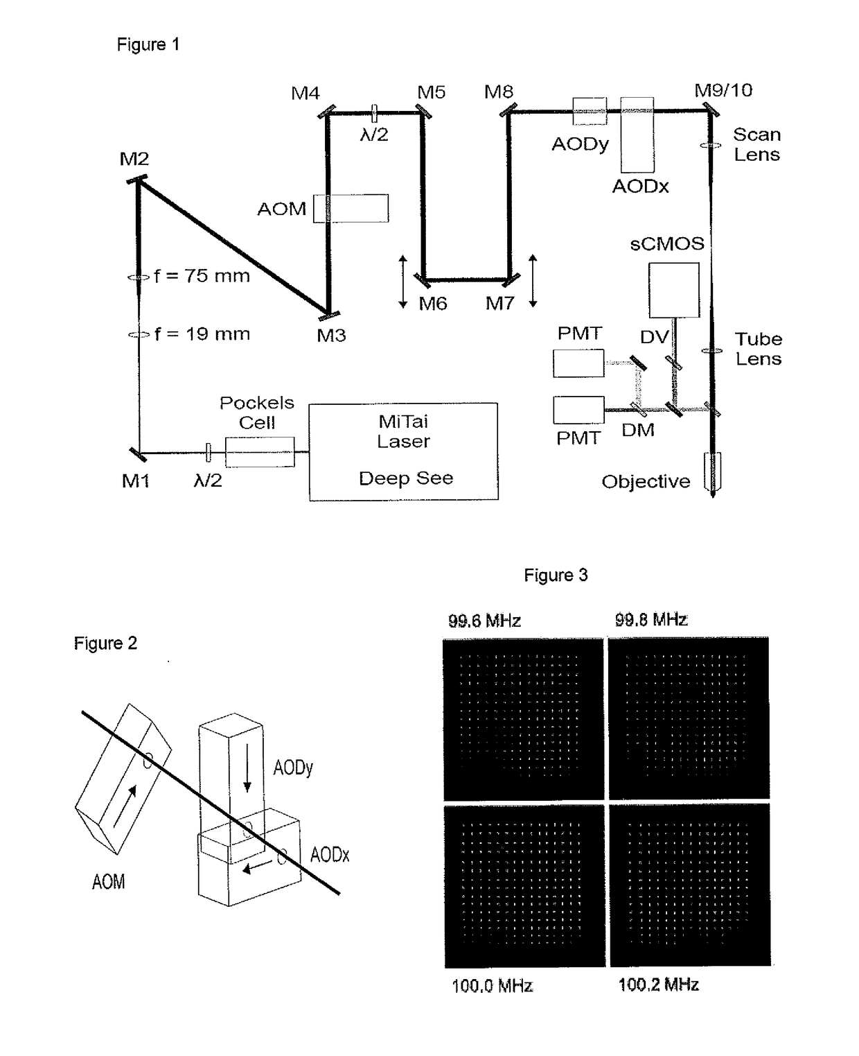
[0024]FIG. 2 is an expanded schematic illustration of the relative orientation of the AOM and the AODs in FIG. 1;

[0025]FIG. 3 illustrates the compensation of spatial dispersion of the beam resulting from applying an acoustic compensation signal at various constant frequencies over a grid of illumination points;

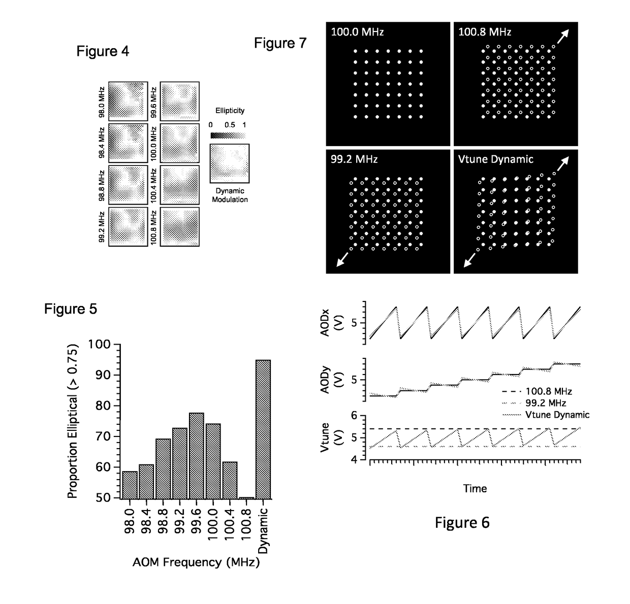
[0026]FIG. 4 illustrates the ellipticity of the beam at each illumination point over the full field of view resulting from applying an acoustic compensation signal at various constant frequencies over a grid of illumination points compared with using dynamic modulation of the an acoustic compensation signal frequency;

[0027]FIG. 5 illustrates t...


PUM

PropertyMeasurementUnit
frequencyaaaaaaaaaa
frequencyaaaaaaaaaa
frequencyaaaaaaaaaa

Abstract

An apparatus (10) for structured illumination microscopy (SIM) comprises a pulsed femtosecond MiTai laser (11) operable to generate a pulsed beam. The beam pulses are directed on to a specimen (12) via an optical arrangement including a beam steering apparatus comprising a pair of acousto-optic deflectors AODx, AODy, each operable to vary the deflection angle of the beam in response to variation in the frequency of an applied acoustic deflection signal,and an acousto-optic modulator AOM. The frequency of the acoustic deflection signals applied to the AODs and/or the frequency of the acoustic compensation signal applied to the AOM in the present invention is dynamically modulated. This dynamic modulation can increase the effective AODxy scan angle in each direction by about 4 mrads (equivalent to a 15% increase in the area of the field of view). Furthermore, dynamic modulation of the compensation frequency also improves the evenness of the illumination over the field of view.

Description

TECHNICAL FIELD OF THE INVENTION[0001]The present invention relates to improvements in or relating to super-resolution microscopy, in particular to a form of structured illumination, random access microscopy (Super-RAMP) and most particularly to an improved method and apparatus for structured illumination of specimens utilising acousto-optic deflectors (AODs).BACKGROUND TO THE INVENTION[0002]Random access microscopy (RAMP) relies upon positioning a point of illumination rapidly over a specimen with a programmable beam steering arrangement. Light emitted by the specimen is then detected with a camera or other detection source. For Super-RAMP microscopy, points of sparse illumination are scanned rapidly over the specimen. Subsequently, a sequence of images from the camera can be used to produce high-resolution, optically sectioned images.[0003]One beam steering arrangement used in such techniques comprises one or more acousto-optic deflectors (AODs) operable to vary the deflection ang...

Claims


Application Information

Patent Timeline
Patent Type & Authority Applications(United States)
IPC IPC(8): G02F1/33G02B27/58G02B21/00
CPCG02F1/33G02B27/58G02B21/0032G02B21/0036G02B21/0084
Inventor HARTELL, NICHOLAS ANTHONY
Owner UNIVERSITY OF LEICESTER
Why Eureka
Try Eureka