Check patentability & draft patents in minutes with Patsnap Eureka AI!

Flex flat cable structure and flex flat cable electrical connector fix structure

Active Publication Date: 2017-05-04
ENERGY FULL ELECTRONICS CO LTD
View PDF15 Cites 5 Cited by
  • Summary
  • Abstract
  • Description
  • Claims
  • Application Information

AI Technical Summary

Benefits of technology

The present patent is about improving the transmission loss and withstanding current capacity of high-speed data transmission flat cables and power wires. This is achieved by broadening the size of metallic transmission wires, replacing the insulating jacket material or foaming it. The patent also adds an embossment pattern on the external surface of the insulating jacket to improve heat dissipation capability and withstanding current capability. The proposed FFC electrical connector fix structure also increases the distance of transmission for a flat cable signal and narrows the size of a flat cable more easily. Overall, the patent enables easier and more flexible wiring with improved performance.

Problems solved by technology

Besides, the resistance of the flat copper wire is greater under the limit of impedance specifications so the FFC is not beneficial to transmitting a high-speed data signal for a long distance.
But, it should be taken into consideration that high costs and the difficulty in compression if other insulating material is substituted for the FFC.
However, the increase in the quantity or width of the flat copper wire is disadvantageous of narrowing the size of the FFC.

Method used


Image

  • Flex flat cable structure and flex flat cable electrical connector fix structure
  • Flex flat cable structure and flex flat cable electrical connector fix structure
  • Flex flat cable structure and flex flat cable electrical connector fix structure

Examples


first embodiment

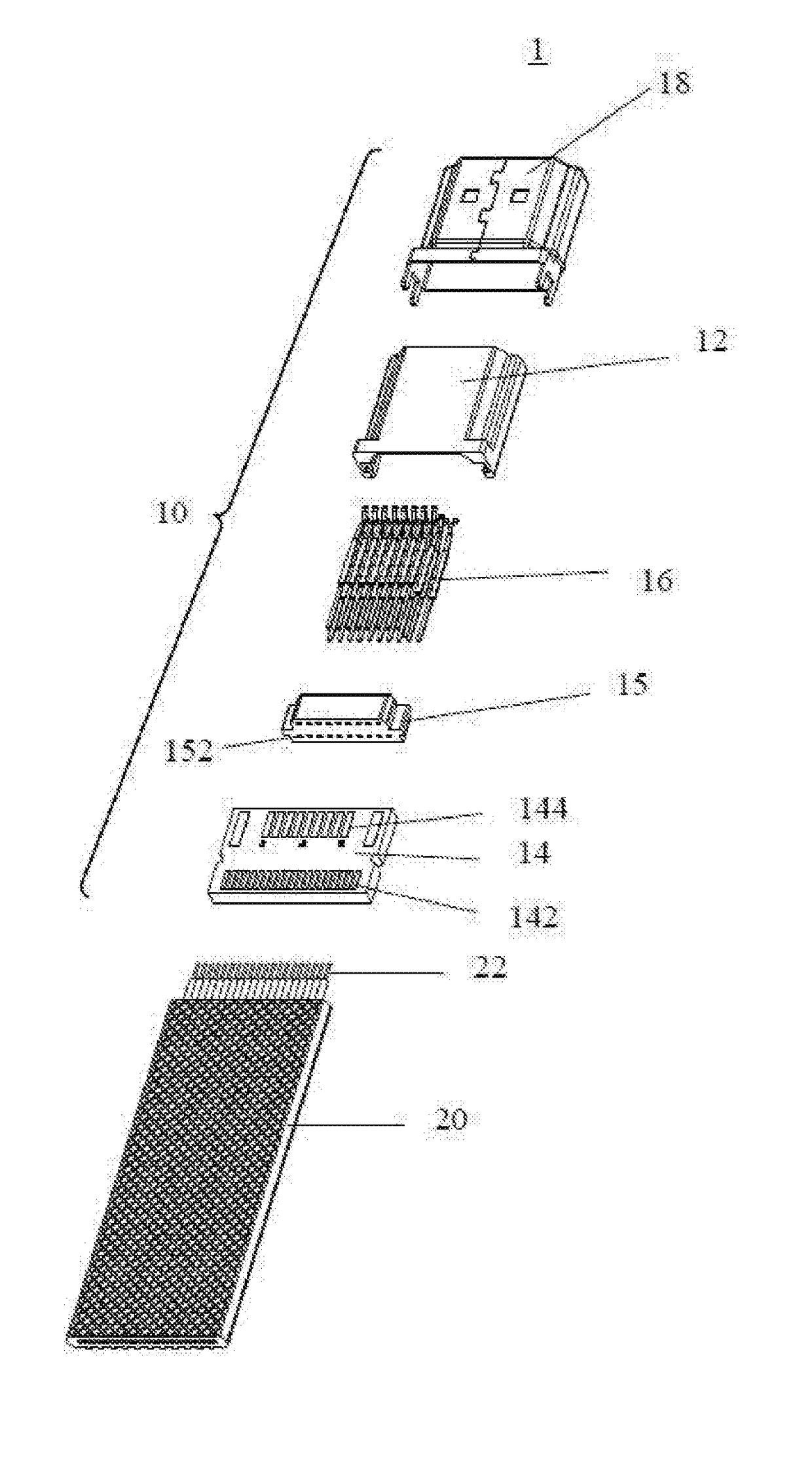
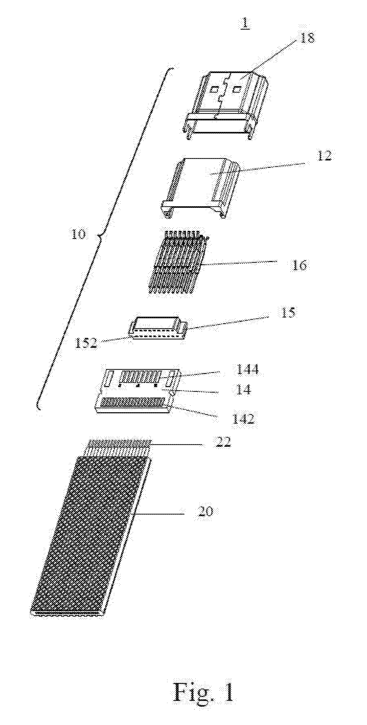
[0033]Please refer to FIG. 2. FIG. 2 is a cross-sectional view of a flex flat cable (FFC) structure 20a according the present disclosure. The FFC structure 20a comprises a plurality of metallic transmission wires 22, a plurality of first insulating jackets 241, and a second insulating jacket 242. The plurality of metallic transmission wires 22 are arranged parallel. The metallic transmission wire 22 comprises one or more power wires 222 and a plurality of signal wires 224. The power wire 222 is used to transmit power, and the signal wire 224 is used to transmit a data signal. The profile of the metallic transmission wire 22 looks like a round. One of the plurality of metallic transmission wires 22 is enclosed by each of the plurality of first insulating jackets 241. The plurality of first insulating jackets 241 are enclosed by the second insulating jacket 242. An embossment pattern 248 is arranged on the external surface at both sides of the second insulating jacket 242. In this emb...

second embodiment

[0034]Material of the first insulating jacket 241 is different from that of the second insulating jacket 242. Preferably, the first insulating jacket 241 and the second insulating jacket 242 may be insulating materials with highly thermal resistance such as polyethylene (PE), polyvinyl chloride (PVC), Thermoplastic Elastomer (TPE), Thermoplastic Polyurethane (TPU), thermoplastic rubber (TPR), Thermoplastic Polyolefin (TPO), Polyurethane (PUR), Polypropylene (PP), Polyolefins (PO), PolyVinyliDene Fluoride (PVDF), Ethylene-chlorotrifluororthylene copolymer (ECTFE), ethylene-tetra-fluoro-ethylene (ETFE), Teflon Fluorinated ethylene propylene (Teflon FEP), Polytetrafluoroethene (PTFE), Teflon, and nylon. The metallic transmission wire 22 may be a highly thin, flat tinned copper wire. Please refer to FIG. 3. FIG. 3 is a cross-sectional view of a flex flat cable (FFC) structure 20b according the present disclosure. The FFC structure 20b comprises a plurality of metallic transmission wires...

third embodiment

[0036]Please refer to FIG. 4. FIG. 4 is a cross-sectional view of a flex flat cable (FFC) structure 20c according the present disclosure. The FFC structure 20c comprises a plurality of transmission line sets 21, a plurality of first insulating jackets 241, and a second insulating jacket 242. Each of the plurality of the transmission line sets 21 comprises a plurality of metallic transmission wires 22. The plurality of metallic transmission wires 22 are arranged parallel. The metallic transmission wire 22 comprises one or more power wires 222 and a plurality of signal wires 224. The power wire 222 is used to transmit power, and the signal wire 224 is used to transmit a data signal. The profile of the metallic transmission wire 22 looks like a round. The two or more metallic transmission wires 22 in each of the plurality of the transmission line sets 21 are enclosed by the plurality of first insulating jackets 241. The other metallic transmission wires 22 in each of the plurality of t...


PUM


Abstract

A flex flat cable (FFC) structure includes metallic transmission wires arranged in parallel, first insulating jackets, and second insulating jacket. The metallic transmission wires includes one or more power wires and signal wires. The power wire is configured to transmit power. The signal wires are configured to transmit a data signal. Each of first insulating jackets encloses one of metallic transmission wires. The second insulating jacket surrounds the first insulating jackets. An embossment pattern is arranged on an external surface of the second insulating jacket. The embossment pattern includes meander lines in a top-view direction and in an extending direction for the metallic transmission wires. The meander lines are not arranged parallel.

Description

CROSS REFERENCE TO RELATED APPLICATIONS[0001]This application claims the benefit of U.S. Provisional Application Ser. No. 62 / 250,837 filed on Nov. 4, 2015, which is incorporated herein their entirety.BACKGROUND OF THE INVENTION[0002]1. Field of the Invention The present disclosure relates to a flex flat cable (FFC) structure, and more particularly, to an FFC structure having a surface where an embossment pattern is formed.[0003]2. Description of the Prior Art[0004]A flex flat cable (FFC) is a new type data line cable. The FFC is fabricated by an insulating material and a highly thin, flat tinned copper wire after the insulating material and the flat tinned copper wire are compressed in an automation device. A core is neatly arranged in the FFC, largely transmitted, structurally flat, compact in size, dismantled easily, and flexible so the FFC can be applied to all kinds of electronic products easily and flexibly. So the FFC as a data transmission cable is especially suitable for dif...

Claims


Application Information

Patent Timeline
IPC IPC(8): H01B7/08H01B3/18H01B7/04H01R12/77H01B9/00H01B9/02H01B7/18H02G15/076H01B7/02
CPCH01B7/0823H02G15/076H01B3/18H01B7/04H01R12/777H01B7/0225H01B9/003H01B9/028H01B7/1805H01B7/0216H01B7/0208H01B7/17H01B7/421H01R12/00H01R12/62H01B7/184H01B7/426
Inventor CHIN, HSU-SHEN
Owner ENERGY FULL ELECTRONICS CO LTD
Features
  • R&D
  • Intellectual Property
  • Life Sciences
  • Materials
  • Tech Scout
  • Unparalleled Data Quality
  • Higher Quality Content
  • 60% Fewer Hallucinations
Learn More