Check patentability & draft patents in minutes with Patsnap Eureka AI!

Power electronic assembly

a technology of electronic components and components, applied in the direction of cooling/ventilation/heating modifications, semiconductor/solid-state device details, modification by conduction heat transfer, etc., can solve the problems of sudden device failure or a reduced operational life, imperfect contact between two surfaces, and reduced safe operating area, etc. cost-effective, easy to manufacture, the effect of relatively low unit cos

Active Publication Date: 2017-05-04
ABB (SCHWEIZ) AG
View PDF17 Cites 7 Cited by
  • Summary
  • Abstract
  • Description
  • Claims
  • Application Information

AI Technical Summary

Benefits of technology

The patent describes a way to improve the thermal connection between a semiconductor module and a heat sink using a layer of metal foil and lubricant coating. This helps prevent deformation of the heat sink during highly cyclic loading of the module. Additionally, the lubricant layer also helps reduce mechanical stress during installation. The use of aluminum sheet with a lubricant layer is cost-effective and easy to manufacture. Overall, this improves the overall performance and reliability of the thermal interface.

Problems solved by technology

A violation of the temperature ratings can lead to a reduced safe operating area and consequently a sudden device failure or to a reduced operational lifetime.
In practice the contact of two surfaces is imperfect and there are gaps filled with air in between them.
However, the base plate footprint size of PE modules is several times larger compared to CPU's footprint size.
This initial out-of-planarity causes uneven contact pressure at module mounting.
This dynamic behavior causes complex deformation scenario to the thermal interface, which loads the TIM, and in many cases destroys TIM's capability to carry out the heat conduction function.
As during the power cycling shear stresses are applied to the thermal interface material, the thermal interface material breaks down and loses its ability to conduct the heat effectively from the base plate to the cooling arrangement.
This in turn leads to increase of temperature of the switching components and to premature breakdown of the components.

Method used


Image

  • Power electronic assembly
  • Power electronic assembly
  • Power electronic assembly

Examples


Embodiment Construction

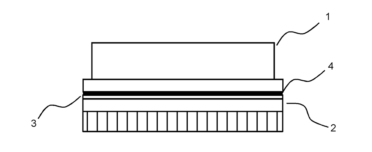
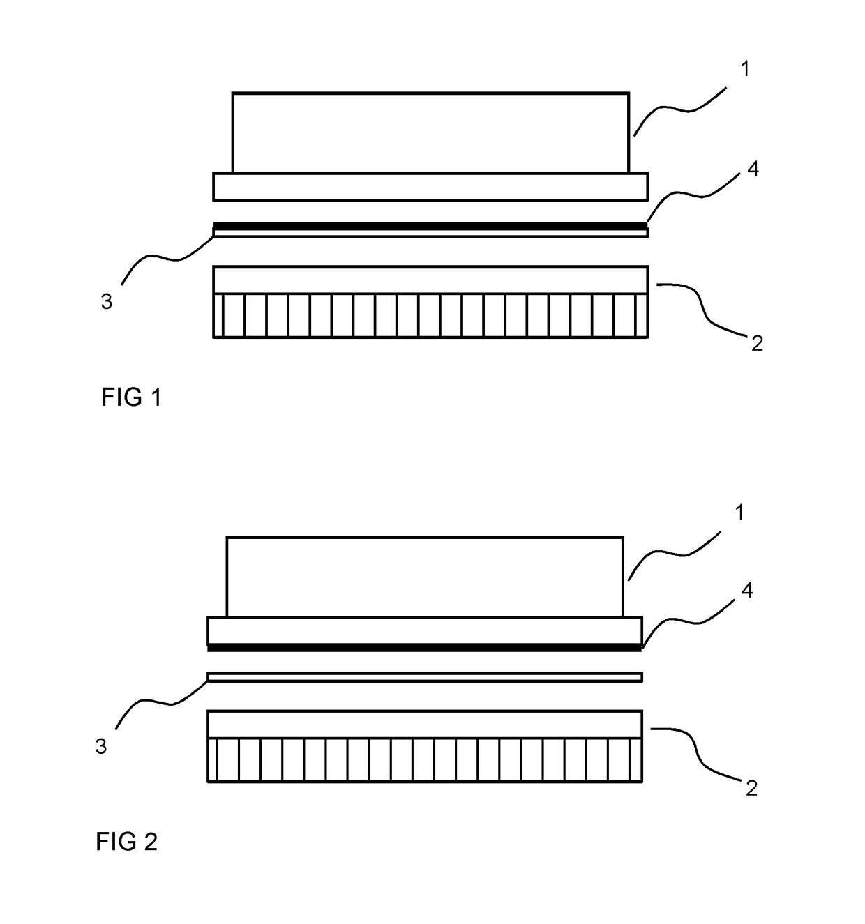
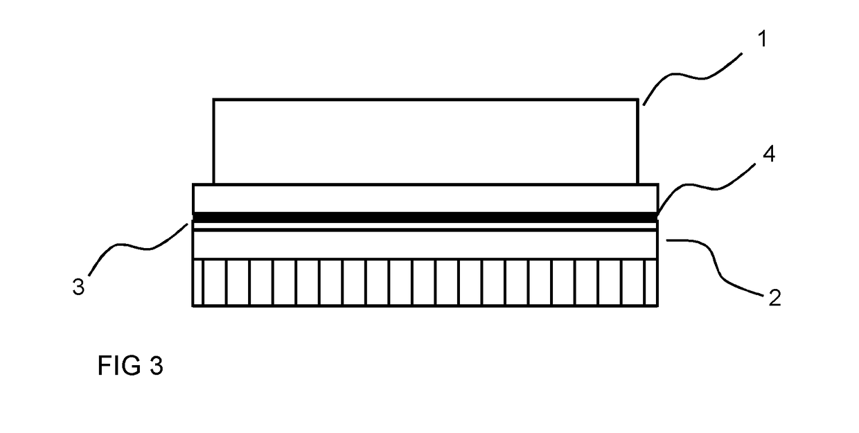
[0019]FIGS. 1 and 2 show a basic structure of a power electronic assembly according to an embodiment. In FIGS. 1 and 2 the main parts of the structure are shown as separated from each other whereas in FIG. 3, the assembly is completed. The power electronic assembly comprises a power electronic module 1, cooling arrangement 2 and a thermal interface material comprising a metal foil 3 and a layer of solid lubricant 4. The power electronic module is a component enclosing multiple of power electronic switches. Such modules are used in building power electronic devices which large currents are switched and which use high voltages. Typical way of operating such power semiconductor switches is to have the component either fully conducting or blocking such that current is flowing through the component only when the voltage across the component is close to zero. Although the components are controlled in such a manner that losses are minimized, some losses are incurring both during the switch...


PUM


Abstract

A method of producing a power electronic assembly and a power electronic assembly comprising a power electronic module incorporating multiple of semiconductor power electronic switch components, the power electronic module comprising a base plate with a bottom surface, the power electronic assembly comprises further a cooling arrangement for cooling the power electronic module, the cooling arrangement comprising a cooling surface adapted to be attached against the bottom surface of the base plate of the power electronic module, wherein the power electronic assembly comprises further a thermal interface material arranged between the bottom surface of the base plate of the power electronic module and the cooling surface of the cooling arrangement to transfer heat from the power electronic module to the cooling arrangement, the thermal interface material comprises a metal foil and a solid lubricant coating.

Description

FIELD OF THE INVENTION[0001]The present invention relates to power electronics components, and more particularly to thermal interface materials to be used in connection with power electronics components.BACKGROUND OF THE INVENTION[0002]Power electronic modules are widely used components in which multiple of power electronic switches or devices are placed in a single module. The switches of a power electronic module are wired inside the module in specified manner such that power electronic modules can be used in different circuit structures. Such circuit structures are, for example, power stages of different power converters. For that purpose, the power electronic modules may comprise different half-bridge, full bridge or other bridge topologies in which controllable switch components are internally connected with power diodes. The power electronic modules comprise also terminals, such as control terminals and power terminals that allow connecting the modules to other required circui...

Claims


Application Information

Patent Timeline
IPC IPC(8): H01L23/367H01L25/00H01L25/07H01L23/373H01L29/739H01L21/48
CPCH01L23/3672H01L29/7393H01L25/50H01L25/07H01L23/3736H01L21/4882H05K7/2039H05K7/209H01L23/3735H01L23/3737H01L23/42
Inventor MANNINEN, JORMAMYLLYKOSKI, PIRKKA
Owner ABB (SCHWEIZ) AG
Features
  • R&D
  • Intellectual Property
  • Life Sciences
  • Materials
  • Tech Scout
  • Unparalleled Data Quality
  • Higher Quality Content
  • 60% Fewer Hallucinations
Learn More