System and method for determining vapor pressure of produced hydrocarbon streams via spectroscopy

a technology of vapor pressure and hydrocarbon streams, which is applied in the field of system and method for determining vapor pressure of produced hydrocarbon streams via spectroscopy, can solve the problems of loss of revenues and potential emission issues, affecting the measurement of the rvp of stabilized condensate, and affecting the quality of hydrocarbons, so as to achieve the effect of reducing interferen

Active Publication Date: 2017-05-11
JP3 MEASUREMENT
View PDF6 Cites 13 Cited by
  • Summary
  • Abstract
  • Description
  • Claims
  • Application Information

AI Technical Summary

Benefits of technology

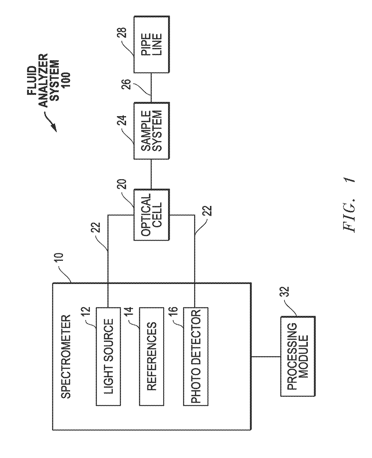
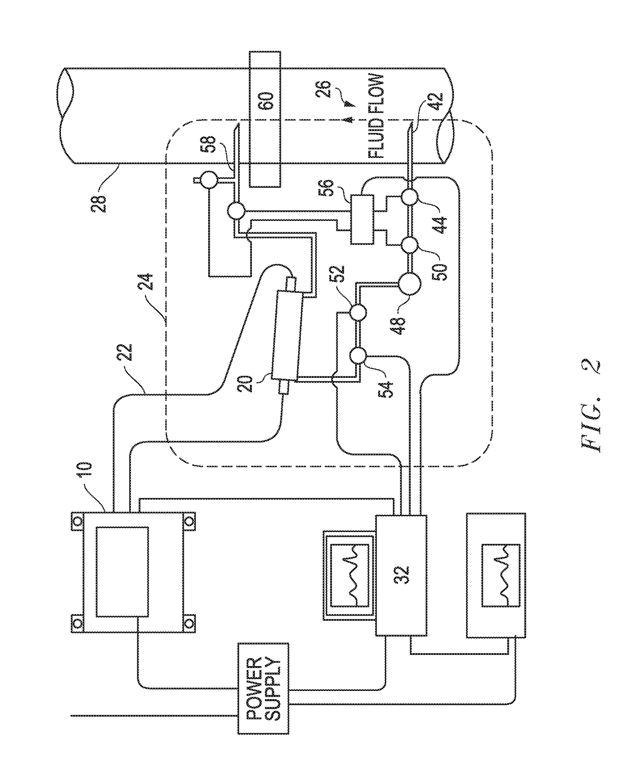
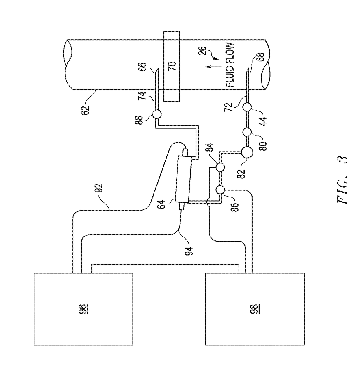
[0015]In one embodiment, an NIR analyzer is installed with the optical probes across the pipe or with bypass configuration after a stabilizer of an oil or condensate production plant. Prior to use, liquid samples from the plant are analyzed in a chemical lab to obtain reference vapor pressure or compositional values. A chemometric model using known techniques such as partial least square, classic least squares or principle component regression, is then built with the captured absorption spectra and the reference lab results. The spectra can be subject to preprocessing methodologies, such as first and second or derivatives, extended multiplicative scattering correction, mean centering, and auto scaling, to name a few. The preprocessing methodologies can be used to help mitigate interferences such as cloudiness, or optical transmissibility, of the fluid, instrument drift, and contaminate build up on the lenses in contact with the fluid. The preprocessing methodologies also act as noise filters to enable models to focus on the real compositional changes in the fluid that may affect the resultant vapor pressure of the liquid. After that, the chemometric model is implemented to the NIR analyzer as the calibration curve to predict the vapor pressure or other values of the flowing fluid in real time.

Problems solved by technology

The issue with condensate in its natural form is that the lighter hydrocarbons can make it dangerous to store and transport.
Often, the condensate is pumped to a sales storage tank, where it will flash off its lighter hydrocarbon components, which usually are captured through vapor recovery compression in order to prevent venting to the atmosphere, which results in lost revenues and potential emission issues.
Measuring the RVP of stabilized condensate in the midstream gathering and stabilization facilities of the more recent shale oil fields has proven to be a very difficult analysis due to the amount of paraffin in the condensate stream.
True Vapor Pressure (“TVP”) is also of interest, but is much more difficult to determine in the field as it is a partial pressure calculation based on compositional analysis performed to determine the individual components of a complex fluid.
This demanded significant resources and, by definition, could not provide continuous vapor pressure values for a flowing line or a transportation or storage vessel in the field.
Additionally, excessive care must be taken using extractive sampling methodologies to ensure that the sample taken to the lab is representative of the process stream.
Fluids with high vapor pressures, which are the most critical to monitor, are subject to contamination and vapor loss leading to erroneous results, due to the propensity of the lighter molecules to “flash-off” during the sampling process or in transport to the lab.
This can result in a lower vapor pressure reading than was actually present at the time of sample extraction.
One of the biggest issues with these online analyzers is paraffin build-up in the system.
As the temperature of the product is brought down to the 100° F. required for measurement, the paraffinic material has a tendency to drop out and clog the system, requiring extensive intervention to get back online.
Also, it can take considerable time for the conventional online analyzer to complete the analysis.
Measuring vapor pressure in the field under real pressure and temperature conditions is nearly impossible to model or calculate based on compositional values.

Method used


Image

  • System and method for determining vapor pressure of produced hydrocarbon streams via spectroscopy
  • System and method for determining vapor pressure of produced hydrocarbon streams via spectroscopy
  • System and method for determining vapor pressure of produced hydrocarbon streams via spectroscopy

Examples


Embodiment Construction

[0033]The present invention is directed to improved methods and systems for, among other things, determining vapor pressure of produced hydrocarbon streams via spectroscopy. The configuration and use of the presently preferred embodiments are discussed in detail below. It should be appreciated, however, that the present invention provides many applicable inventive concepts that can be embodied in a wide variety of contexts other than as described herein. Accordingly, the specific embodiments discussed are merely illustrative of specific ways to make and use the invention, and do not limit the scope of the invention. In addition, the following terms shall have the associated meaning when used herein:

[0034]“fluid infrastructure” means any infrastructure used in connection with the collection, processing, storage, transmission or distribution of a fluid including, without limitation, if the fluid is a hydrocarbon, any infrastructure between the wellhead and the point of retail delivery...


PUM

PropertyMeasurementUnit
wavelength rangeaaaaaaaaaa
Reid vapor pressureaaaaaaaaaa
temperatureaaaaaaaaaa

Abstract

An NIR analyzer with the optical probes across a pipe, or in a bypass configuration, after a stabilizer in an oil or condensate production plant. Prior to use, liquid samples from the plant are analyzed in a chemical lab to obtain reference vapor pressure or compositional values. A chemometric model using known techniques is then built with the captured absorption spectra and the reference lab results. Preprocessing methodologies can be used to help mitigate interferences of the fluid, instrument drift, and contaminate build up on the lenses in contact with the fluid. The chemometric model is implemented through the NIR analyzer as the calibration curve to predict the vapor pressure or other values of the flowing fluid in real time.

Description

CROSS-REFERENCE TO RELATED APPLICATIONS[0001]This application is a divisional based upon prior U.S. patent application Ser. No. 14 / 609,191, filed Jan. 29, 2015 in the name of Joseph Paul Little, III and Jie Zhu, entitled “System and Method for Determining Vapor Pressures of Produced Hydrocarbon Streams via Spectroscopy,” which claims priority based upon prior U.S. Provisional Patent Application Ser. No. 61 / 933,150 filed Jan. 29, 2014 in the name of Joseph Paul Little, III and Jie Zhu, entitled “System and Method for Determining Reid Vapor Pressure,” the disclosure of which is incorporated herein by reference.BACKGROUND OF THE INVENTION[0002]In fluid processing plants, the plant operating company may or may not own all of raw feed stock. Feeds may come from differing sources, and the operating contracts for product fluids may be different for varying sources. Also, the economics of operation are dependent on inlet compositions, flow rates, current prices on various spot markets, and ...

Claims


Application Information

Patent Timeline
Patent Type & Authority Applications(United States)
IPC IPC(8): G01N7/14G01N21/359G01N33/28G01N21/3577
CPCG01N7/14G01N21/3577G01N2201/06113G01N33/2829G01N2201/129G01N21/359G01N33/22
Inventor LITTLE, III, JOSEPH PAULZHU, JIE
Owner JP3 MEASUREMENT
Why Eureka
Try Eureka