Apparatus and Methods for Low PAPR Transmission in MIMO Systems

a technology of apparatus and methods, applied in the field of wireless communication, can solve problems such as design challenges of radio equipment, and achieve the effects of increasing the peak-to-average power ratio, adding cost, and increasing the power ratio

Active Publication Date: 2017-05-11
HUAWEI TECH CO LTD
View PDF1 Cites 32 Cited by
  • Summary
  • Abstract
  • Description
  • Claims
  • Application Information

AI Technical Summary

Benefits of technology

[0003]In accordance with an embodiment, a method performed by a network entity for configuring transmission in a multiple-input and multiple-output (MIMO) system is disclosed. The method includes obtaining a signal to be transmitted by a first set of antennas of the network entity, and determining a penalty to add cost for one or more portions of the signal that are projected on one or more of the antennas in the first set with higher peak-to-average power ratio (PAPR) than remaining portions of the signal. The method further includes obtaining a penalized signal to be transmitted by a second set of antennas in accordance with the penalty. The penalized signal has a smaller PAPR than the obtained signal.
[0004]In accordance with another embodiment, a network component supporting transmission in a MIMO system is disclosed. The network component comprises at least one processor coupled to a memory, and a non-transitory computer readable storage medium storing programming for execution by the at least one processor. The programming including instructions to obtain a signal to be transmitted by a first set of antennas of the network component, and determine a penalty to add cost for one or more portions of the signal that are projected on one or more of the antennas in the first set with higher PAPR than remaining portions of the signal. The instructions also configured the network component to obtain a penalized signal to be transmitted by a second set of antennas in accordance with the penalty. The penalized signal has a smaller PAPR than the obtained signal.
[0005]In accordance with another embodiment, a method performed by a network entity for configuring transmission in a MIMO is disclosed. The method includes determining a time domain penalty for a time domain signal to be transmitted by a first set of antennas of the network entity. The time domain penalty determined to add cost to one or more portions of the time domain signal that are projected on one or more of the antennas in the first set with higher PAPR than remaining portions of the time domain signal. The method further includes translating the time domain penalty into a frequency domain penalty, and obtaining a penalized frequency domain signal to be transmitted by a second set of antennas in accordance with the frequency domain penalty. The penalized frequency domain signal has a smaller peak-to-average power ratio (PAPR) than the time domain signal.
[0006]In accordance with another embodiment, a network component supporting transmission in a MIMO system is disclosed. The network component comprises at least one processor coupled to a memory, and a non-transitory computer readable storage medium storing programming for execution by the at least one processor. The programming includes instructions to determine a time domain penalty for a time domain signal to be transmitted by a first set of antennas of the network component. The time domain penalty is determined to add cost to one or more portions of the time domain signal projected on one or more of the antennas in the first set with higher PAPR than remaining portions of the time domain signal. The programming includes further instructions to translate the time domain penalty into a frequency domain penalty, and obtain a penalized frequency domain signal to be transmitted by a second set of antennas in accordance with the frequency domain penalty. The penalized frequency domain signal has a smaller PAPR than the time domain signal.
[0007]In accordance with an embodiment, a method performed by a network entity for configuring transmission in a MIMO system is disclosed. The method includes clipping a time domain signal to a determined saturated level, wherein the clipped time domain signal has a smaller PAPR than the time domain signal, and projecting, using MIMO precoding, the adjustment signal for the clipped time domain signal on a plurality of antennas for transmission. The adjustment signal is obtained in accordance with a constellation deviation due to distortion in the clipped time domain signal.
[0008]In accordance with yet another embodiment, a network component supporting transmission in a MIMO system is disclosed. The network component comprises at least one processor coupled to a memory, and a non-transitory computer readable storage medium storing programming for execution by the at least one processor. The programming includes instructions to clip a time domain signal to a determined saturated level. The clipped time domain signal has a smaller PAPR than the time domain signal, and project, using MIMO precoding, an adjustment signal for the clipped time domain signal on a plurality of antennas for transmission. The adjustment signal is obtained in accordance with a constellation deviation due to distortion in the clipped time domain signal.

Problems solved by technology

However, due to the utilization of MU-MIMO especially at the presence of multi-carrier modulation schemes such as OFDM, the M-MIMO scheme suffers from high peak-to-average power ratio (PAPR) in transmitted signals, which is undesirable and causes challenges in designing the radio equipment.

Method used


Image

  • Apparatus and Methods for Low PAPR Transmission in MIMO Systems
  • Apparatus and Methods for Low PAPR Transmission in MIMO Systems
  • Apparatus and Methods for Low PAPR Transmission in MIMO Systems

Examples


Embodiment Construction

[0020]The making and using of the presently preferred embodiments are discussed in detail below. It should be appreciated, however, that the present invention provides many applicable inventive concepts that can be embodied in a wide variety of specific contexts. The specific embodiments discussed are merely illustrative of specific ways to make and use the invention, and do not limit the scope of the invention.

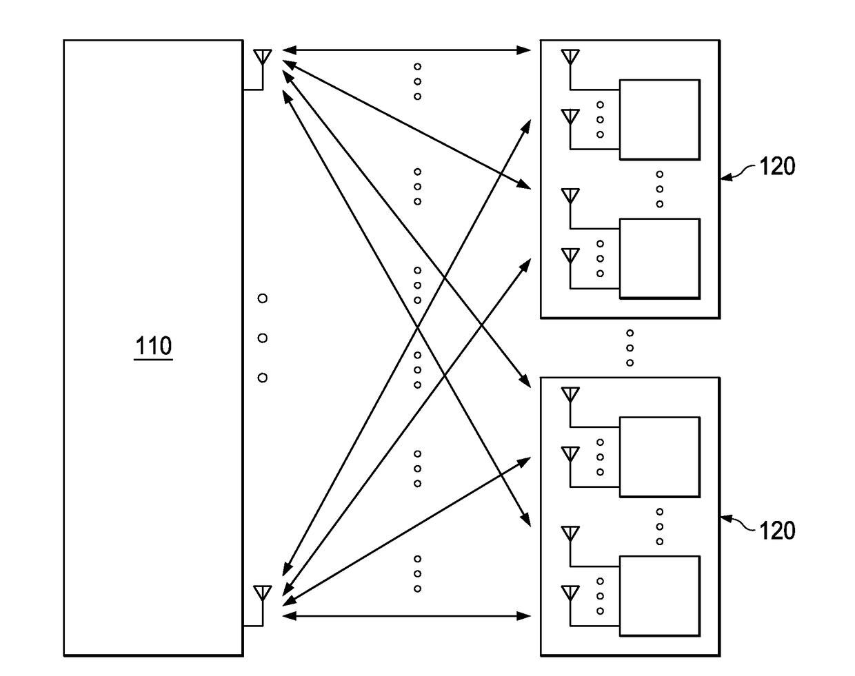
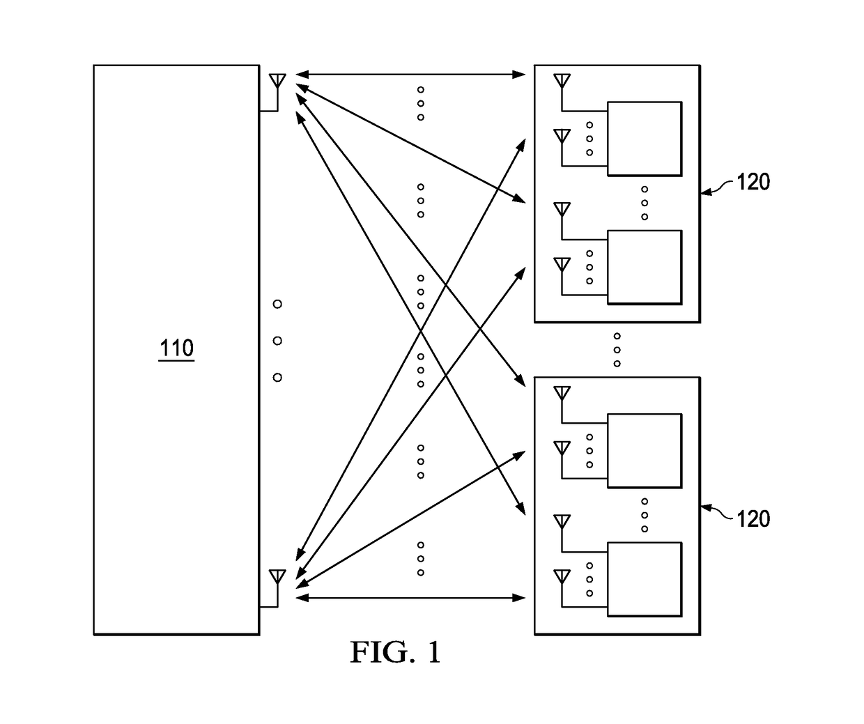
[0021]FIG. 1 shows a MIMO communications system including a radio access network (RAN) node 110 and one or more UEs 120. The RAN node 110 is also referred to in scenarios as a base station (BS) or a transmission point (TP). Although one RAN node 110 is shown, the system may include any number of RAN nodes 110. Examples of the RAN node 110 include a nodeB, an evolved nodeB (eNB), a WiFi TP, or any other type of network node capable of exchanging wireless signals with the UE 120. Examples of the UE 120 include a smartphone, a mobile phone, a laptop computer, a tablet computer, ...


PUM


Abstract

System and method embodiments are provided herein for achieving low peak-to-average power ratio (PAPR) signals in multiple-input and multiple-output (MIMO) systems, including Massive MIMO (M-MIMO) systems. The embodiments include two schemes to reduce the PAPR in the transmitted signals. In a first scheme, the signals are precoded, at a BS or UE, to offload a signal from one antenna to another antenna to achieve PAPR reduction. The precoding is done with some penalty in terms of signal gain. In a second scheme, the signal is clipped and the clipped portion is further projected on the MIMO antennas to compensate for the error caused by clipping. Out-of-band radiation is also removed in this scheme.

Description

TECHNICAL FIELD[0001]The present invention relates to wireless communications, and, in particular embodiments, to apparatus and methods for low peak-to-average power ratio (PAPR) Transmission in multiple-input and multiple-output (MIMO) systems.BACKGROUND[0002]In MIMO systems, the capacity of a radio link is multiplied or increased using multiple transmit and receive antennas to exploit multipath propagation in various orientations or directions. A base station or user equipment (UE) can send and / or receive more than one data signal on the same radio channel at the same time using multipath propagation. Massive MIMO (M-MIMO) is an advanced MIMO technique that can be used in current and next generation wireless communication systems. In M-MIMO, a set of antennas is used with corresponding radio frequency (RF) amplifiers to increase gain in transmitted signal power. Each M-MIMO antenna or a group of antennas is driven by a RF amplifier. With the availability of many antennas at the ne...

Claims


Application Information

Patent Timeline
Patent Type & Authority Applications(United States)
IPC IPC(8): H04L27/26H04B7/04
CPCH04B7/0456H04L27/2614
Inventor BALIGH, MOHAMMADHADI
Owner HUAWEI TECH CO LTD
Why Eureka
Try Eureka