Solid chemicals injection system for oil field applications

a technology of solid chemicals and injection systems, which is applied in the direction of pipeline systems, chemistry apparatuses and processes, and well accessories, etc., can solve the problems of reducing the pumping efficiency and flow of oil through the drilling, production and tubular systems, and contaminant precipitation, so as to reduce stoppages, increase accuracy and efficiency, and save energy

Active Publication Date: 2017-05-25
CHAMPIONX USA INC
View PDF1 Cites 5 Cited by
  • Summary
  • Abstract
  • Description
  • Claims
  • Application Information

AI Technical Summary

Benefits of technology

[0013]The system further can include a valve and a pressure component, both in communication with the open interior volume of the receptacle. The valve is adapted for enabling discharge of the liquid phase chemical into the oilfield fluid stream in predetermined doses. The pressure component is operably connected to the receptacle and adapted to apply pressure on at least a portion of the chemical loaded in the open interior volume, aiding in delivering melted chemical to the injection port.
[0023]The method further includes discharging the liquid phase chemical into the oilfield fluid in predetermined doses using a valve in fluid communication with the open interior volume. In some embodiments, the method comprises injecting an effective amount of the molten chemical into the oilfield fluid stream to sufficiently prevent, decrease or inhibit foulant and / or contaminant deposits.
[0025]In these and various other embodiments, the method further includes applying pressure upon at least a portion of the solid chemical in the first volume using a pressure component. The applied pressure aids in melting, delivering and injecting the liquid chemical. Increased pressure can further be applied to reduce the energy required to melt the solid chemical in the first volume and to increase the rate of flow of liquid chemical through the system.
[0027]In further embodiments, the chemical delivery apparatus further comprises a discharge conduit and a discharge heating component. The discharge conduit is in fluid communication with the outlet conduit and is operably connected to the valve at a first end and adapted for operable connection to the injection port at a second end for discharging of the liquid phase chemical. The discharge heating component is adapted for preventing solidification of liquid phase chemical within the discharge conduit.
[0038]Use and application of the systems, apparatus and methods of the present invention provide advantages in the areas of dosage accuracy, efficiency, safety and costs related to materials, equipment and labor. The invention greatly reduces the need for shipping and storing large volumes of liquid chemicals, provides for a safer and more efficient and economical manner of oil well remediation than is possible with current methods. The melting and discharging of the chemical can be performed contemporaneously for as long as is required for sufficient dosing, reducing stoppages. The receptacle can be refilled with solid chemical if needed. The valve regulated flow allows for controlled and accurate dosages, increasing accuracy and efficiency. This further provides the user with current information regarding volumes discharged and volumes available. The targeted and continuous heating with concurrent discharge further provides economic benefit in that energy use is kept at a minimum, since only a portion of the receptacle is heated; and in that the user can melt only the volume of inhibitor to be injected in the immediate future. This significantly reduces energy requirements, as opposed to maintaining a whole receptacle of inhibitor constantly above its melting temperature. If, after use, there remains unused chemical, since the chemical is in solid form, absent substantive solvent content, it can be safely stored in the receptacle, without waste or degradation of the chemical.

Problems solved by technology

When crude oil is pumped from a formation and transported via drilling and production tubulars and transmission pipelines, these contaminants can precipitate out due to changes in pressure and temperature.
This can result in the deposition of such contaminants throughout the system of drilling and production tubulars and pipelines.
As these various deposits buildup, they can occlude the various tubulars and deposit on inner surfaces of flow lines, valves and pumps, greatly reducing the pumping efficiency and flow of oil through the drilling, production and tubular systems.
However, each method of addressing contaminant buildup does have its limitations and can involve substantive cost and production downtime.
Determination of the specific contaminant and determination, formulation and transport of an appropriate treatment can be complex and time consuming.
While the use of such chemical additives has shown some effectiveness in inhibiting contaminant depositions, the use of such liquid or solvent based inhibitors greatly increases the cost of transport, storage, and safety of various inhibitor compounds.
This is at least due in part to the large volume of solvent needed to maintain the inhibitor in a liquid state, the volatility of the solvent and the noxious nature of many of the solvents.

Method used


Image

  • Solid chemicals injection system for oil field applications
  • Solid chemicals injection system for oil field applications
  • Solid chemicals injection system for oil field applications

Examples


Embodiment Construction

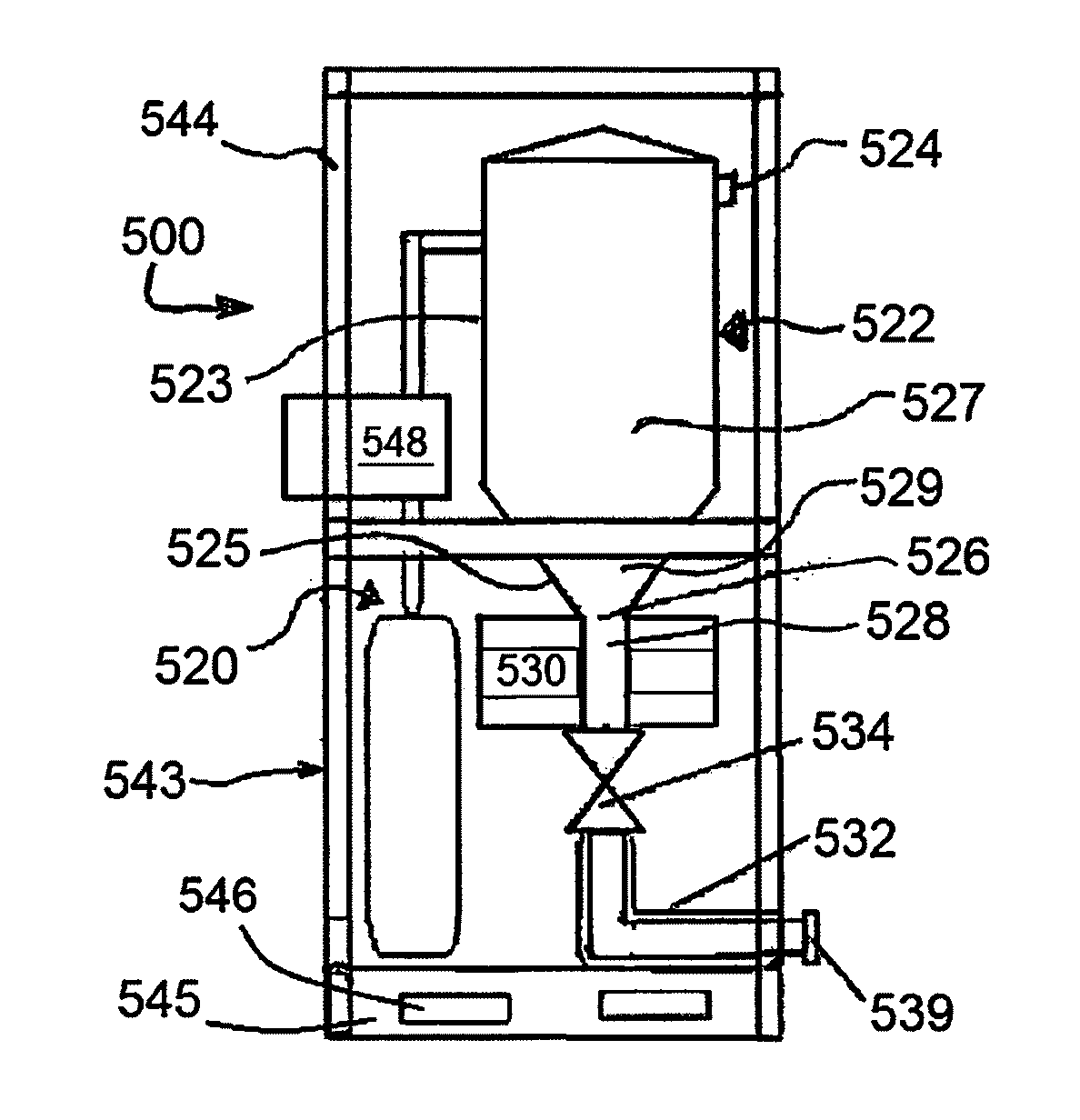
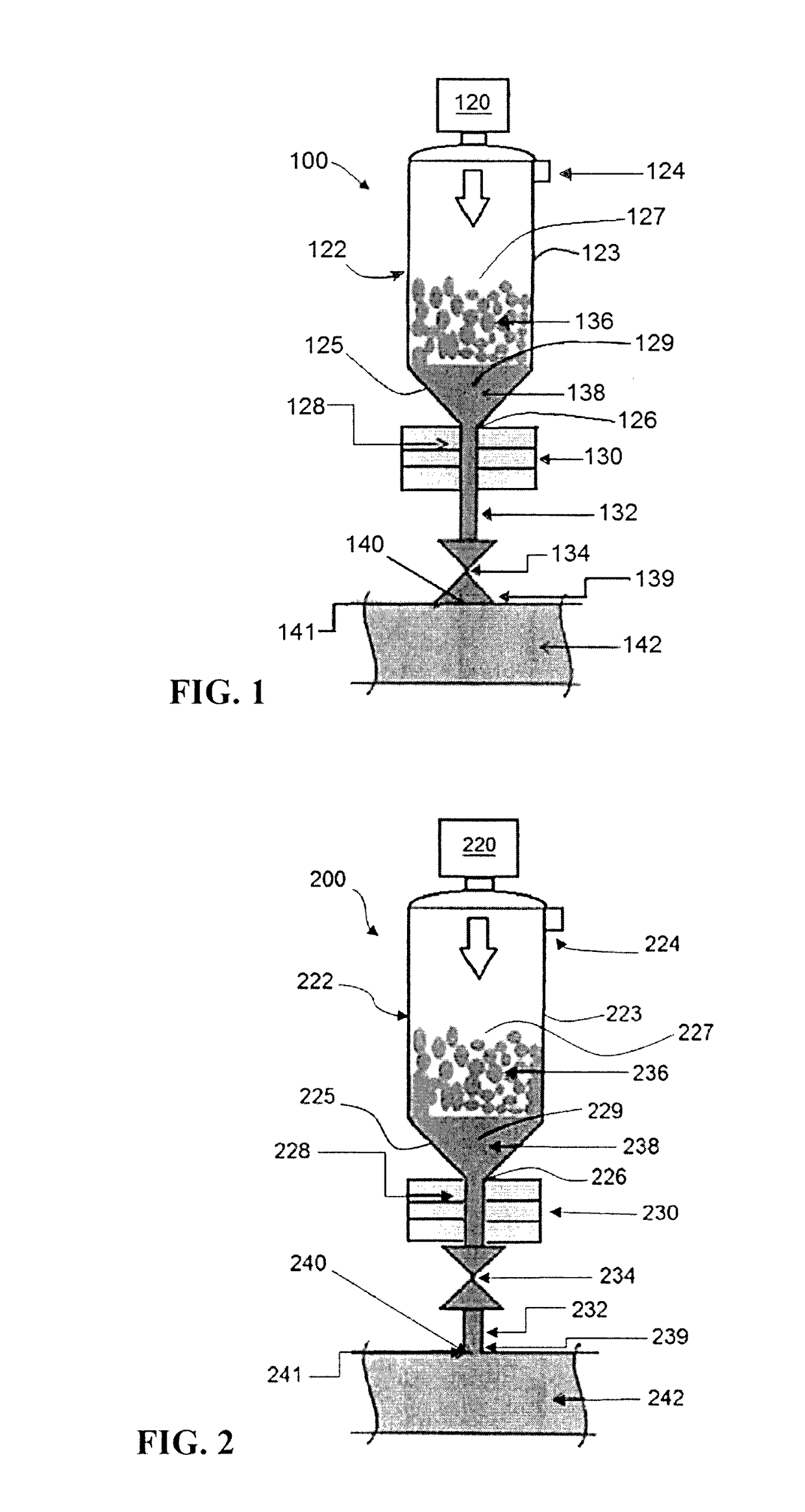
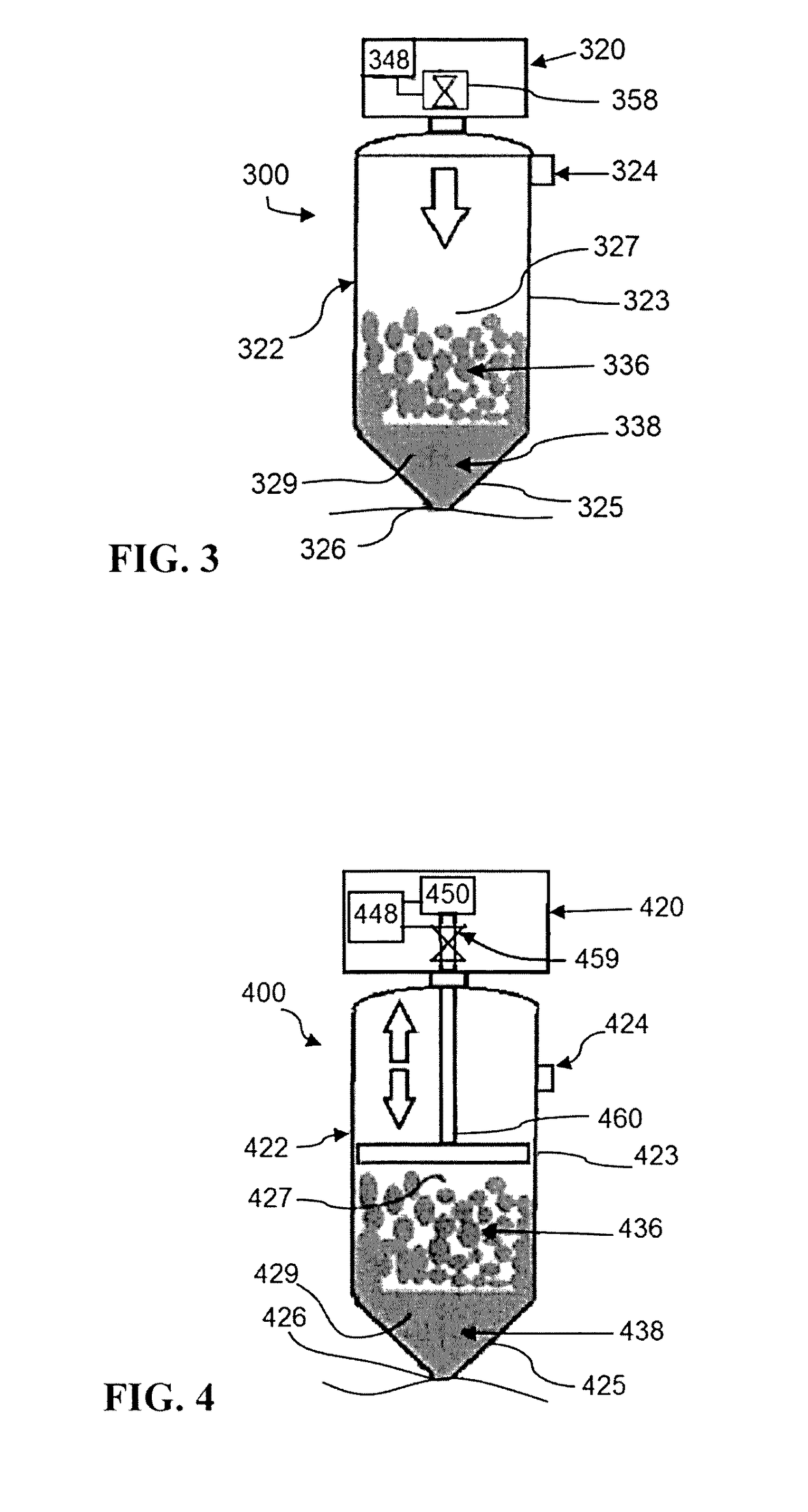
[0046]In various exemplary embodiments, systems, apparatus, and methods according to the invention provide for removing, inhibiting and / or decreasing foulants and / or contaminant precipitated or deposited in oilfield tubulars, pipelines, fittings, wellheads, and the like. Various systems, apparatus and methods according to the invention utilize a chemical injection apparatus and chemicals that are generally solid at ambient temperatures and pressures (approximately 20° C. and 1 atm) and that can be melted and injected by the chemical injection apparatus into the oilfield tubular at the site of use. Thus, the need for shipping large volumes of liquid chemicals and solvents can be greatly reduced, providing a safer and more efficient and economic manner of oilfield remediation than possible with current methods.

[0047]Unless otherwise defined herein, all technical and scientific terms used herein have the same meaning as commonly understood by one of ordinary skill in the art. In case o...


PUM


Abstract

Systems, methods and apparatus using a solid chemical as an injectable for inhibiting, decreasing or preventing precipitation and / or deposition of foulants and / or contaminants in oilfield tubulars. The use of solid chemicals providing ease of shipment, greater economy in storage, shipment and delivery and increased ease of use.

Description

CROSS-REFERENCE TO RELATED APPLICATIONS[0001]Not Applicable.STATEMENT REGARDING FEDERALLY SPONSORED RESEARCH OR DEVELOPMENT[0002]Not Applicable.Field of the Invention[0003]The present disclosure relates generally to systems, methods and apparatus for mitigating wax-related issues in oilfield wells, flow lines, surface equipment and pipelines.BACKGROUND OF THE INVENTION[0004]Crude oil from geological formations can contain a variety of contaminants and foulants, including solid impurities, gasses and minerals. Solid contaminants and foulants can include waxes, asphaltenes, and various hydrates, while contaminating minerals can include sulfur, iron, vanadium, zinc and various mineral / inorganic salts, such as Barite (Barium sulfate), Calcite (Calcium carbonate) and Halite (Sodium chloride). When crude oil is pumped from a formation and transported via drilling and production tubulars and transmission pipelines, these contaminants can precipitate out due to changes in pressure and tempe...

Claims


Application Information

Patent Timeline
Patent Type & Authority Applications(United States)
IPC IPC(8): E21B41/00E21B37/06
CPCE21B37/06E21B41/00C09K8/524F17D1/16C09K2208/20C09K2208/22C09K2208/32F17D1/18
Inventor FOUCHARD, DAVID MARC DANIEL
Owner CHAMPIONX USA INC
Why Eureka
Try Eureka