Refrigeration cycle device

a technology of refrigerant cycle and refrigerant, which is applied in the direction of compression machines with several condensers, light and heating apparatus, transportation and packaging, etc., can solve the problem of insufficient dehumidification of air-conditioned units, more likely to cause temperature distribution in ventilation air cooled by interior evaporators, and worsening refrigerant distribution in interior evaporators

Active Publication Date: 2017-06-01
DENSO CORP
View PDF19 Cites 14 Cited by
  • Summary
  • Abstract
  • Description
  • Claims
  • Application Information

AI Technical Summary

Benefits of technology

[0009]As mentioned above, in the dehumidification heating mode, the refrigeration cycle device described in Patent Document 1 allows one of the refrigerants branched by the branch portion to flow into the high-pressure side refrigerant passage of the internal heat exchanger, and also allows a refrigerant into which the refrigerants are merged in the merging portion to flow in

Problems solved by technology

When such a liquid-phase refrigerant with the high degree of supercooling flows into the interior evaporator, the distributivity of the refrigerant in the interior evaporator is worsened, making it more likely to cause temperature distribution in the ventilation

Method used


Image

  • Refrigeration cycle device
  • Refrigeration cycle device
  • Refrigeration cycle device

Examples


first embodiment

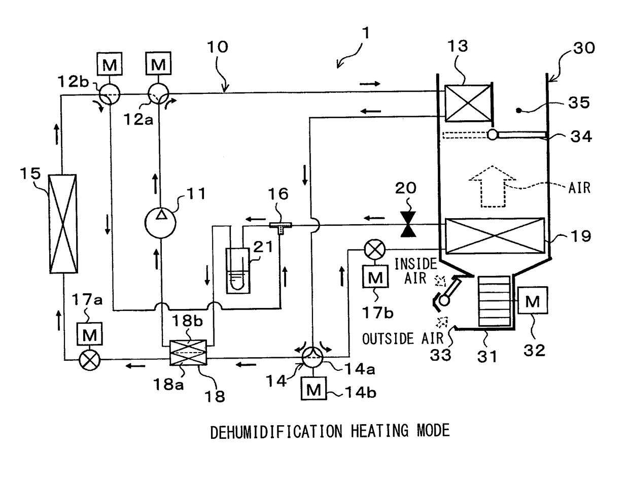
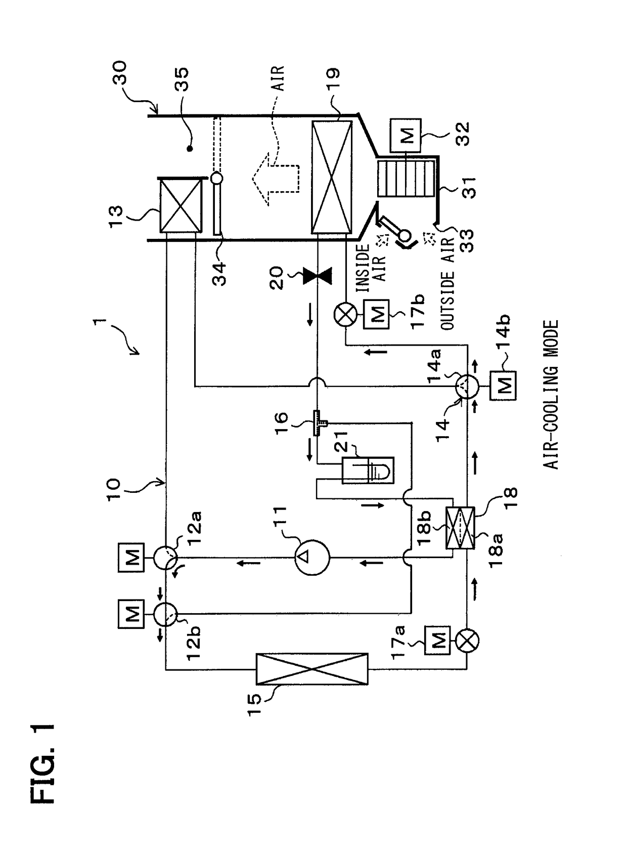
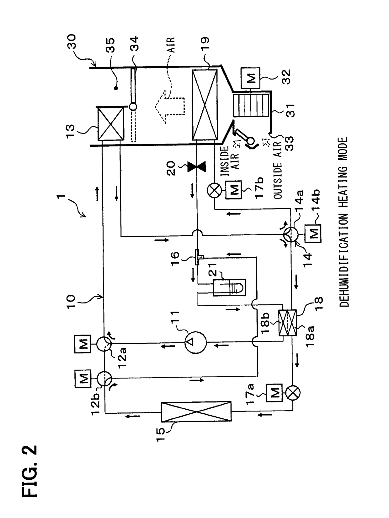
[0041]A first embodiment of the present disclosure will be described below with reference to FIGS. 1 to 5. In this embodiment, a refrigeration cycle device 10 according to the present disclosure is applied to a vehicle air conditioner 1 for an electric vehicle that obtains a driving force for traveling from a traveling electric motor. The refrigeration cycle device 10 in the vehicle air conditioner 1 serves to cool or heat the ventilation air to be blown into the vehicle interior as a space to be air-conditioned.

[0042]The refrigeration cycle device 10 is configured to be switchable between a refrigerant circuit (see FIG. 1) in an air-cooling mode of performing air-cooling of the vehicle interior by cooling the ventilation air and a refrigerant circuit (see FIG. 2) in a dehumidification heating mode of performing dehumidification heating of the vehicle interior by reheating the ventilation air cooled and dehumidified.

[0043]The refrigeration cycle device 10 forms a vapor-compression s...

second embodiment

[0144]This embodiment will describe an example in which the circuit configuration of the refrigeration cycle device 10 is changed from that of the first embodiment, as illustrated in entire configuration diagrams of FIGS. 6 and 7.

[0145]Specifically, the discharge port of the compressor 11 in this embodiment is connected to the refrigerant inlet side of the interior radiator 13. The refrigerant outlet side of the interior radiator 13 is connected to the refrigerant inflow port side of a second three-way joint 16a serving as a branch portion that branches the flow of refrigerant from the interior radiator 13. The second three-way joint 16a has substantially the same basic structure as that of the three-way joint 16 described in the first embodiment.

[0146]In more detail, the second three-way joint 16a uses two of three refrigerant inflow ports as the refrigerant outflow ports and the remaining one as the refrigerant inflow port. Note that in the description below, to clarify the explan...


PUM


Abstract

When performing dehumidification heating of a space to be air-conditioned, a refrigeration cycle device is switched to a refrigerant circuit in which a flow of a refrigerant flowing out of an interior radiator is branched, and one of the branched refrigerants is decompressed by an interior expansion valve to evaporate in an interior evaporator, while the other of the branched refrigerants flows into a high-pressure side refrigerant passage of an internal heat exchanger and is then decompressed by an exterior expansion valve to evaporate in an exterior heat exchanger. Further, in the refrigerant circuit, a flow of the refrigerant flowing out of the interior evaporator and a flow of the refrigerant flowing out of the exterior heat exchanger are merged into a low-pressure side refrigerant passage of the internal heat exchanger. Thus, the refrigerant flowing into the interior evaporator is prevented from becoming a liquid-phase refrigerant having an unnecessarily high degree of supercooling, thereby achieving appropriate dehumidification heating.

Description

CROSS REFERENCE TO RELATED APPLICATION[0001]The application is based on a Japanese Patent Application No. 2014-132115 filed on Jun. 27, 2014, the contents of which are incorporated herein by reference in its entirety.FIELD OF THE INVENTION[0002]The present disclosure relates to a refrigeration cycle device including an internal heat exchanger.BACKGROUND ART[0003]Conventionally, an air-conditioning vapor-compression refrigeration cycle device, which is applied to an air conditioner, is known to include an internal heat exchanger. This kind of internal heat exchanger is designed to exchange heat between high-pressure and low-pressure side refrigerants in a cycle, thereby exhibiting the effect of enlarging a difference in enthalpy (refrigeration capacity) between outlet and inlet-side refrigerants in another heat exchanger serving as an evaporator to improve a coefficient of performance (COP) of the cycle.[0004]For example, Patent Document 1 discloses an air-conditioning refrigeration ...

Claims


Application Information

Patent Timeline
IPC IPC(8): B60H1/00
CPCB60H1/00921B60H1/00392B60H2001/3263B60H2001/00957B60H2001/326B60H1/0075F25B13/00F25B5/02F25B6/02F25B40/00F25B49/02F25B2313/02732B60H1/3207B60H1/3213F25B41/20
Inventor KUWAHARA, MIKIHARU
Owner DENSO CORP
Why Eureka
Try Eureka