Emitting film with improved light-out coupling

a technology of light-out coupling and film, applied in the field of light-out coupling, can solve the problems of energy loss, the selection of a particular polarization for back-illumination, and the loss of about 50% of light emitted by a non-polarized light sour

Active Publication Date: 2017-06-01
YISSUM RES DEV CO OF THE HEBREWUNIVERSITY OF JERUSALEM LTD
View PDF9 Cites 18 Cited by
  • Summary
  • Abstract
  • Description
  • Claims
  • Application Information

AI Technical Summary

Problems solved by technology

In such configuration, the selection of a particular polarization for the back-illumination comes at the cost of energy loss.
Generally, about 50% of light emitted by a non-polarize

Method used


Image

  • Emitting film with improved light-out coupling
  • Emitting film with improved light-out coupling
  • Emitting film with improved light-out coupling

Examples


example

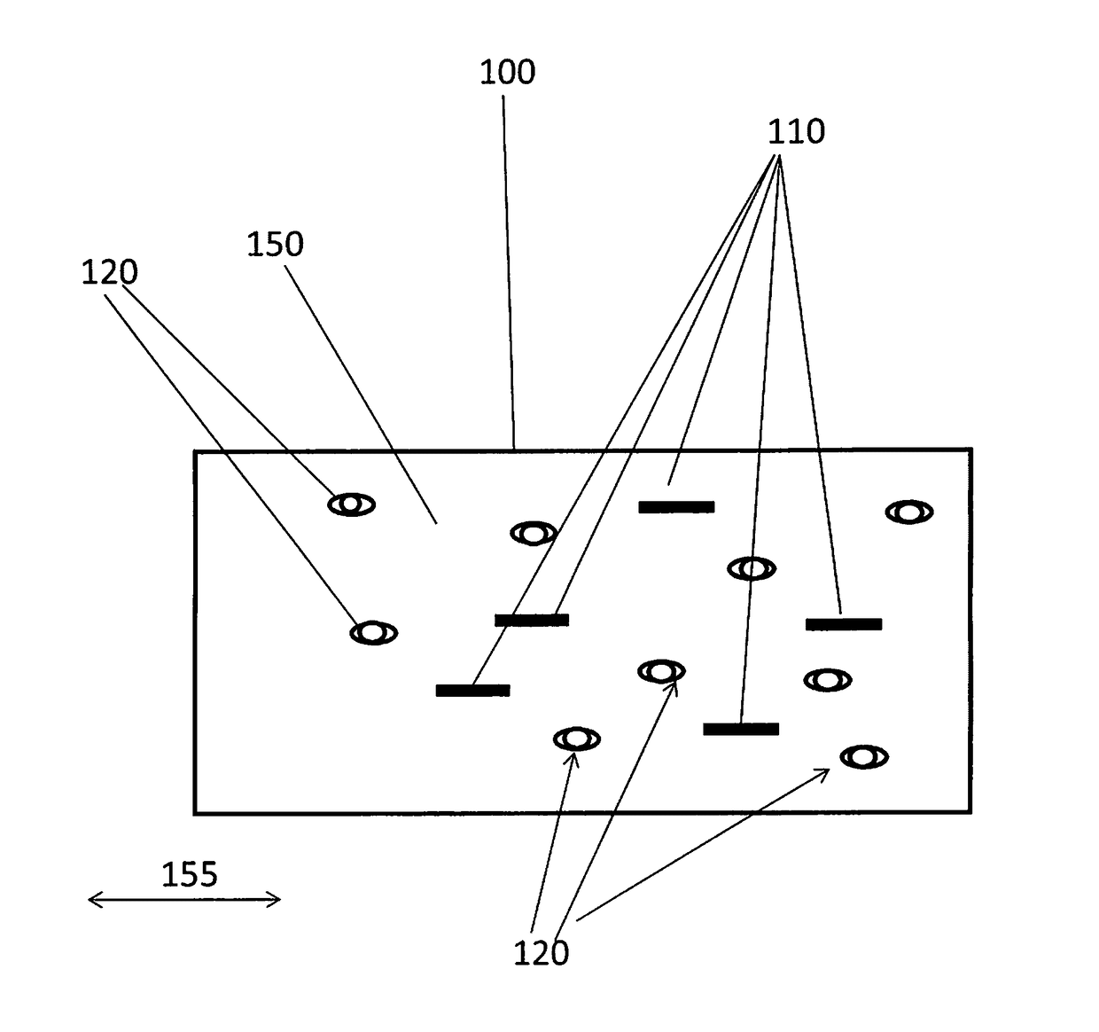
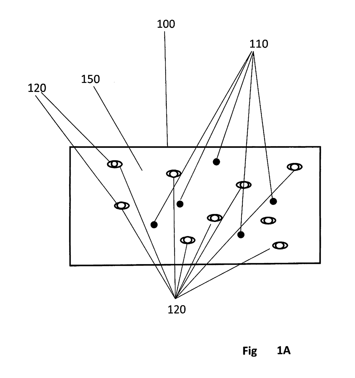
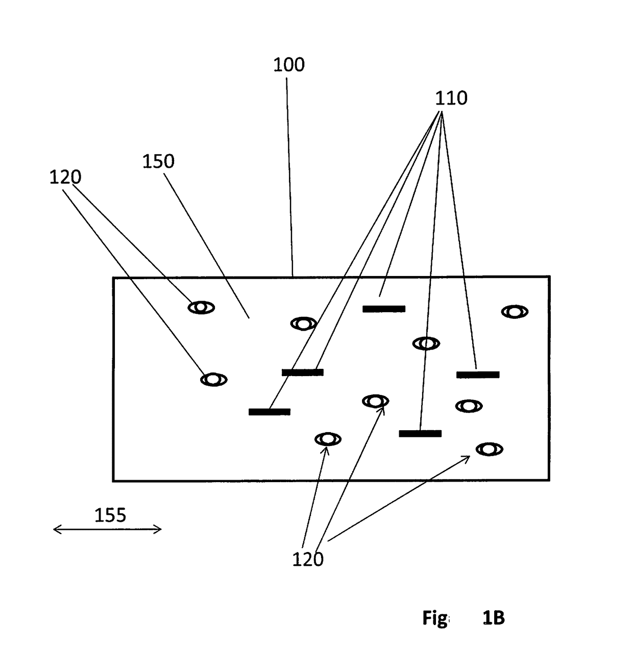
[0088]A layer of the optically active structure, configured for emitting polarized light with efficient light out-coupling was prepared by alignment of nanorods within a polymer matrix which can be made to contain scattering voids. The nanorods were aligned by mechanical stretching of the polymer film. As a first step, the required amount of nanorods and cross-linked PMMA micro-beads (diameter 6 μm, refractive index 1.48, Tg=125° C.) were mixed with an aqueous solution of polyvinyl alcohol (PVA), typically 5-7% wt. The concentration of the beads was 6% wt of the PVA. The mixed solution was then cast into a mold and dried at 40° C. in an oven for 18 hours to form a film having thickness of 50 μm. To align the nanorods, the film was stretched uniaxially at 100° C. by a factor of 3. Since the stretching temperature was above Tg of PVA and below Tg of the PMMA beads, voids were formed around the polymer beads during stretching. The PMMA beads and PVA matrix have similar refractive index...


PUM


Abstract

The present invention provides an optically active structure and the use thereof in a backlight unit. The optically active structure comprises a plurality of optically active particles configured to emit light of one or more predetermined wavelength range in response to pumping energy, and a plurality of light scattering elements. The plurality of light scattering elements comprises optically transparent void regions, such as void regions surrounding filler particles.

Description

TECHNOLOGICAL FIELD[0001]This invention is generally in the field of light source systems, and relates to a light source device configured to emit light. The technique of the invention is particularly useful for a backlight unit in a display device.BACKGROUND ART[0002]References considered to be relevant to the background to the presently disclosed subject matter are listed below:[0003]1. WO 2012 / 059931, Qlight Nanotech[0004]2. U.S. Pat. No. 7,327,415, Rohm and Hass[0005]3. U.S. Pat. No. 6,958,860, Eastman Kodak[0006]4. U.S. Pat. No. 8,197,931, Toray Industries[0007]5. US 2012 / 0113672, Nanosys[0008]6. US 2014 / 0021440, QD Vision[0009]7. WO 2010 / 095140, Qlight NanotechAcknowledgement of the above references herein is not to be inferred as meaning that these are in any way relevant to the patentability of the presently disclosed subject matter.BACKGROUND[0010]Flat-panel displays are widely used in various electronic devices such as computers, mobile phones and televisions sets. Liquid ...

Claims


Application Information

Patent Timeline
IPC IPC(8): F21V9/16G02B1/14G02B5/02F21V11/00F21V9/14
CPCF21V9/16G02B2207/101F21V9/14G02B5/0247G02B1/14G02B5/0268G02B6/0043G02B6/0055G02B6/0053G02F1/133606G02F2001/133614G02B6/0041G02B6/0003G02F1/133611G02F2202/10G02F2203/03F21V11/00G02F2/02G02F2202/108G02F1/133614G02B6/0065
Inventor BANIN, URISHAVIV, EHUDGLOZMAN, DENISARBELL, HAGAI
Owner YISSUM RES DEV CO OF THE HEBREWUNIVERSITY OF JERUSALEM LTD
Why Eureka
Try Eureka