Current detection resistor
a current detection and resistor technology, applied in the direction of resistor details, resistors adapted for applying terminals, instruments, etc., can solve the problems of deterioration of the current detection accuracy of resistors with less than 1 m resistance value, and achieve high current detection accuracy, low resistance value, and large temperature coefficient of resistance
- Summary
- Abstract
- Description
- Claims
- Application Information
AI Technical Summary
Benefits of technology
Problems solved by technology
Method used
Image
Examples
first embodiment
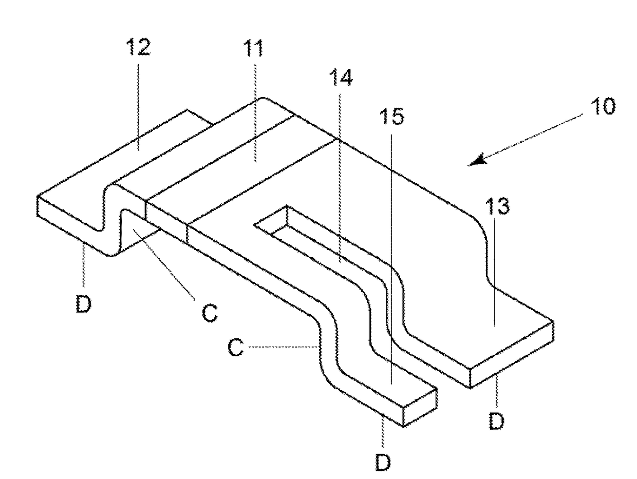
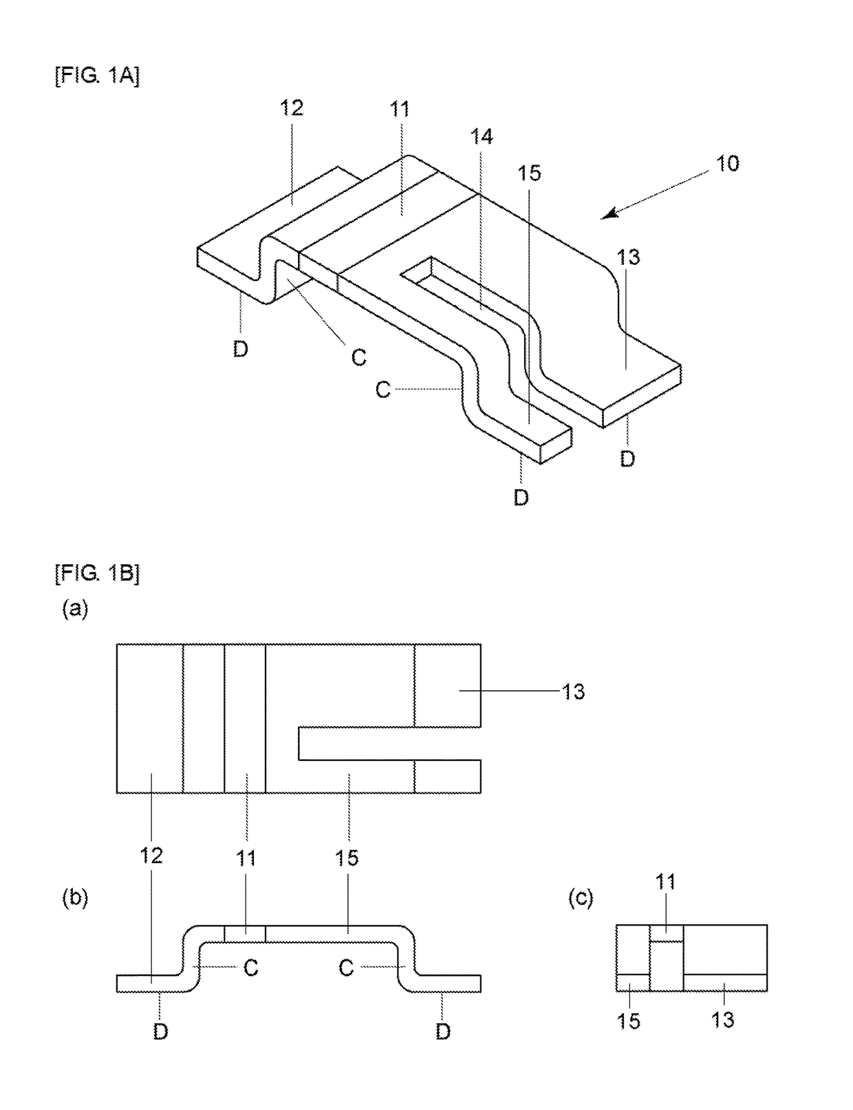
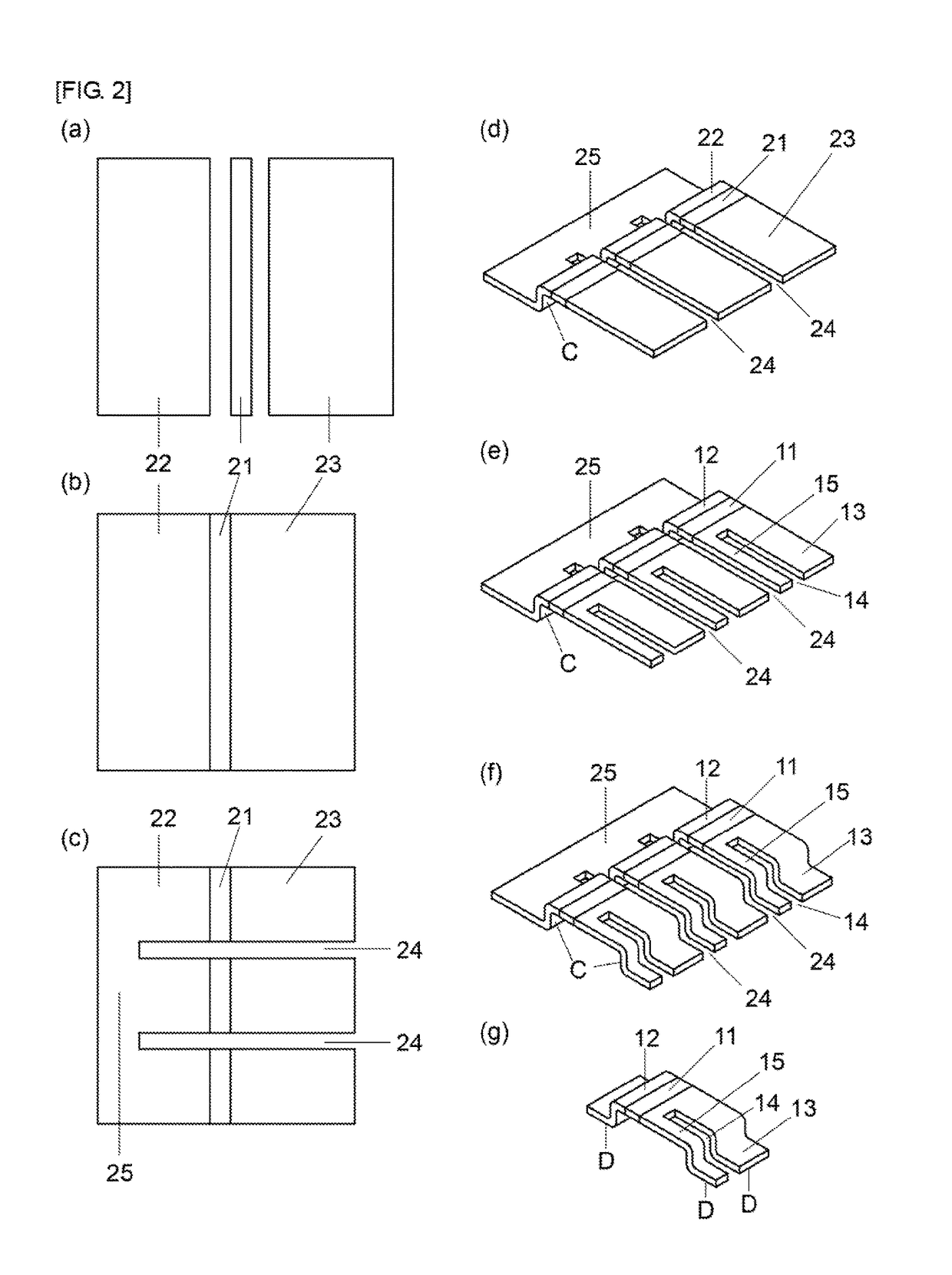
[0025]FIGS. 1A-1B illustrate the current detection resistor of first embodiment of the present invention. The resistor is a metal plate resister including a resistor body 11 consisting of a metal material, a pair of electrodes 12,13 consisting of a metal material, which has higher electrical conductivity than the resistor body, and the resistor body 11 is bonded between the pair of the electrodes 12,13. The resistor body 11 is consisting of a metal material such as Cu—Ni system alloy, Cu—Mn—Ni system alloy, Ni—Cr system alloy, or Fe—Cr system alloy, etc. These material has a low specific resistance value and a small temperature coefficient of resistance, and enables to provide a metal plate resistor having a low resistance value and a small temperature coefficient of resistance.
[0026]Both ends of the resistor body 11 in direction of the current passing through are bonded with a pair of electrodes 12,13 consisting of a metal material such as Cu etc., which has higher electrical condu...
second embodiment
[0036]FIGS. 4A-4B illustrate the resistor 10A of second embodiment of the present invention. In the embodiment, the second electrode 13 is turned as shown in the figure, then the resistor 10A is less likely to be affected by the inductances. The electrode 13 is longer than the other electrode 12, however the slit 14 reaches near the resistor body 11, and then the highly accurate current detection becomes possible as mentioned before.
[0037]It is preferable to fill a resin having excellent thermal conductivity into a space 36 between the resistor body 11 and the second electrode 13. Therefore the heat generated in the resistor body 11 can be dissipated through not only the first electrode 12 side but also the second electrode 13 side and the voltage detection terminal 15 side to the mounting board. Further since the resistor body 11 expands and shrinks vertically by the heat generation, the resistor 10A has an advantage that the stress to the solder bonded portion with the electrode 1...
third embodiment
[0038]FIGS. 5A-5B illustrate the resistor 10B of third embodiment of the present invention. In the embodiment, the resistor body 11 is superposed and bonded between an end of the first electrode 12 and an end of the second electrode 13. That is, one step is formed at a portion where the first electrode 12, the resistor body 11, and the second electrode 13 are superposed, and the other step is formed at bent portion C in the second electrode 13. Thus the resistor 10B has the jumper device function, which strides over a wiring or a component, with the low resistance value resistor function.
[0039]Therefore the length of the resistor body 11 in direction of the current passing through can be shortened (that is, the length can be the thickness of the resistor body 11), and the area of the resistor body 11 perpendicular to the current passing through direction can be large. Then lower resistance value of the resistor 10B such as less than 100 μΩ can be realized. Because of the slit 14 rea...
PUM
 Abstract
Description
Claims
Application Information
 - R&D
- Intellectual Property
- Life Sciences
- Materials
- Tech Scout
- Unparalleled Data Quality
- Higher Quality Content
- 60% Fewer Hallucinations
Browse by: Latest US Patents, China's latest patents, Technical Efficacy Thesaurus, Application Domain, Technology Topic, Popular Technical Reports.
© 2025 PatSnap. All rights reserved.Legal|Privacy policy|Modern Slavery Act Transparency Statement|Sitemap|About US| Contact US: help@patsnap.com


