Ultrasound probe with optimized thermal management

a technology of ultrasonic probes and thermal management, applied in the field of ultrasonic probes, can solve the problems of unsatisfactory thermal build-up in the probe, limiting the acoustic output, rendering the probe cumbersome and complicated, and achieves optimized thermal management and high manoeuvrability.

Active Publication Date: 2017-06-15
ESAOTE
View PDF7 Cites 14 Cited by
  • Summary
  • Abstract
  • Description
  • Claims
  • Application Information

AI Technical Summary

Benefits of technology

[0017]It is thus an object of the present invention to provide a ha...

Problems solved by technology

In both imaging and therapy applications, an undesirable thermal build-up is created in the probe during transmission due to acoustic losses being converted into heat.
Prescribed limits are set or prescribed by governing agencies as to the amount of heat that can be allowed to build up on the surface of the probe, typically limiting the surface temperature of the probe tip to a predetermined temperature or to a predetermined increase above room temperature, and hence limiting the acoustic output.
Although efficient, this system requires an ...

Method used


Image

  • Ultrasound probe with optimized thermal management
  • Ultrasound probe with optimized thermal management
  • Ultrasound probe with optimized thermal management

Examples


Embodiment Construction

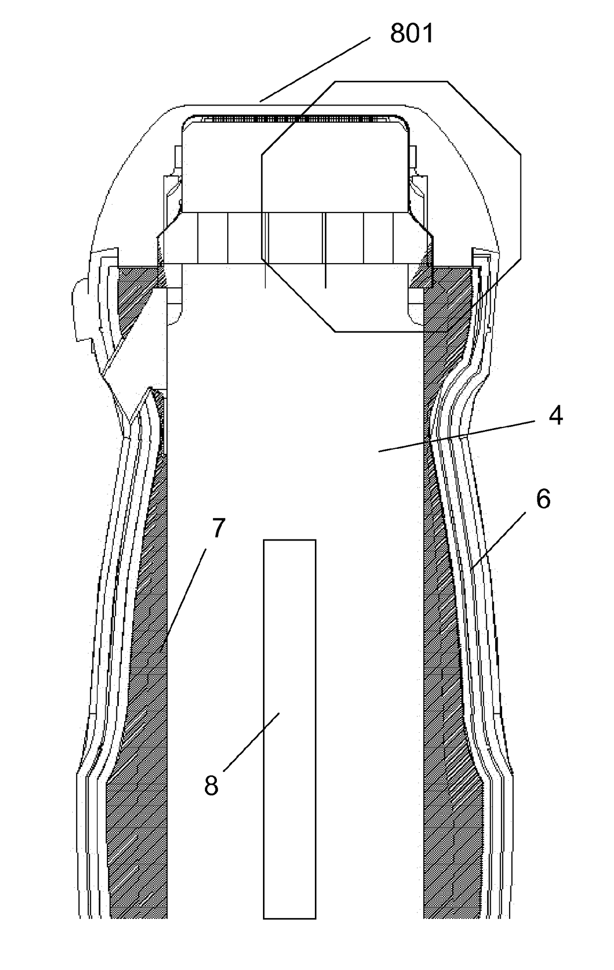
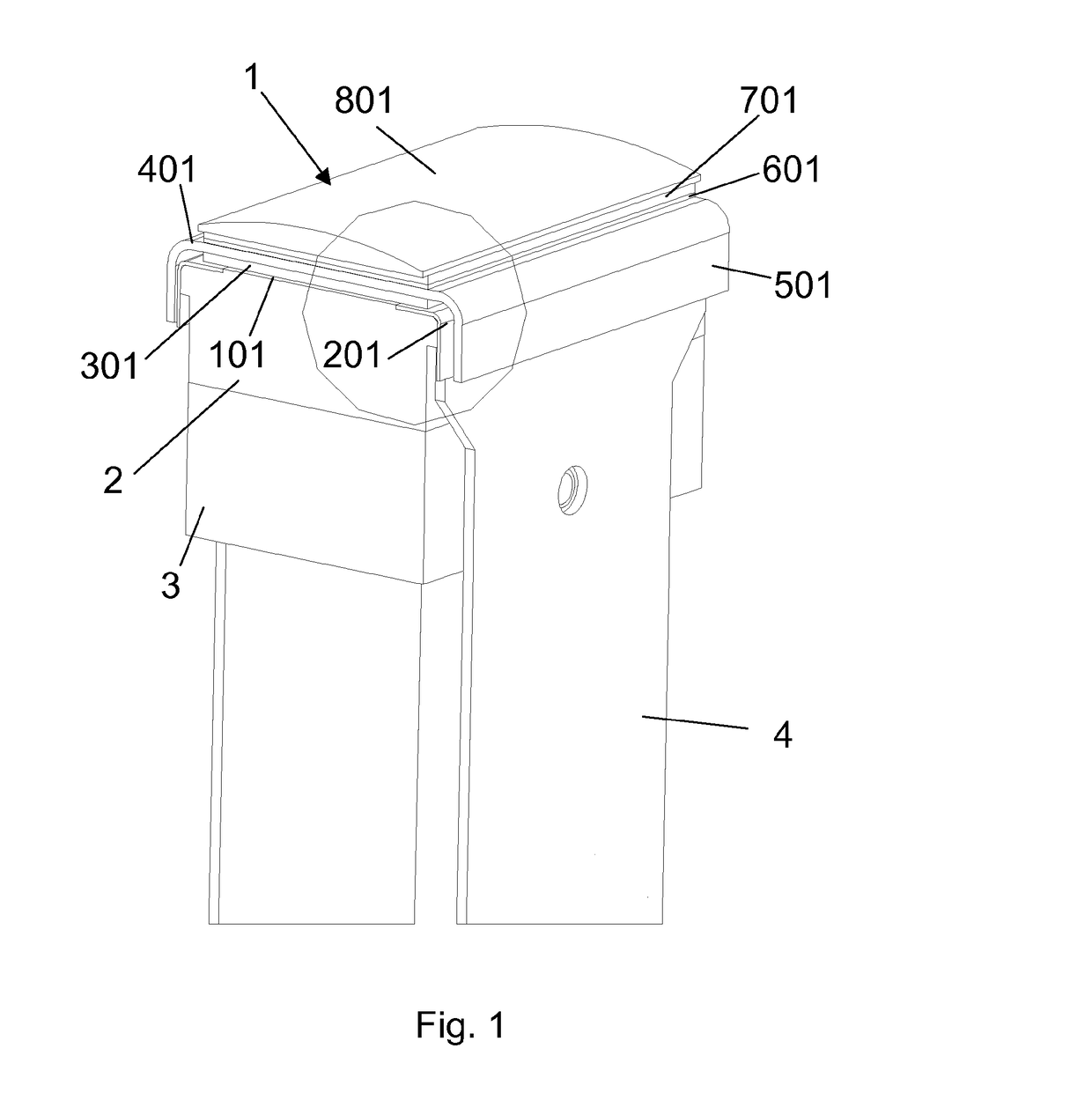
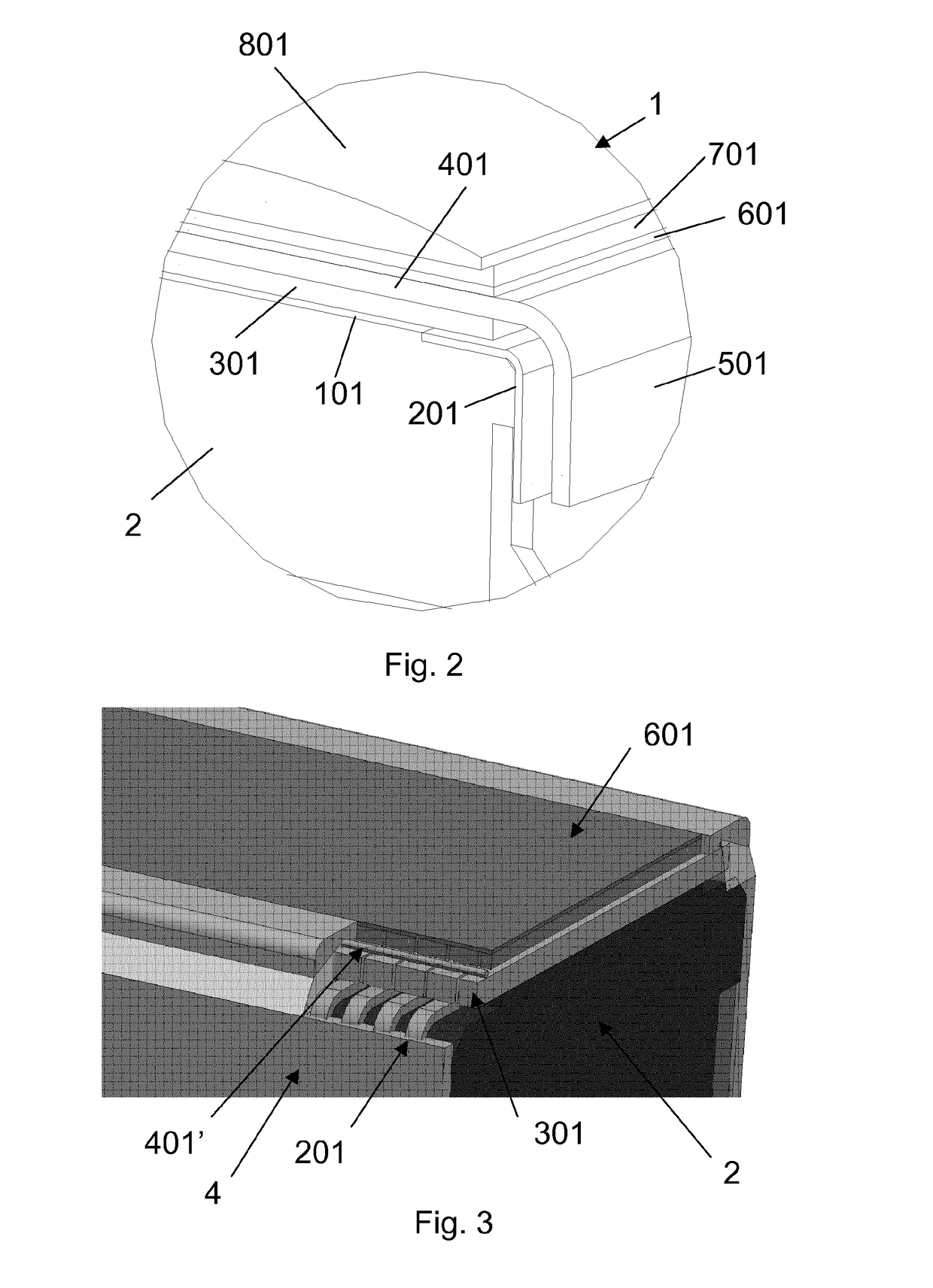
[0046]Referring to FIGS. 1 to 3, a conventional probe is illustrated therein. The probe comprises an ultrasound waves emitting and receiving head 1 which has a front side from which the ultrasound waves are emitted in the direction against a target, such as a body under examination, and on which the reflected ultrasound waves or incoming ultrasound waves impinge and are sensed. The ultrasound head 1 has a back side 3 which is opposite to the said front side and which is oriented towards the inside of a probe casing and towards means for supporting the probe head provided inside the probe casing.

[0047]The probe head 1 comprises, in an order starting from the back side of the said head towards the front side of the said head, which order corresponds also to the direction of propagation of the emitted ultrasound waves, a first layer 101 formed by an array of contact electrodes. Each contact electrode of this layer 101 of contact electrodes has a separate electric connection line to a c...


PUM


Abstract

An ultrasound probe (1) comprising a housing (6), a transducer assembly (301) operable to transmit ultrasonic energy towards a zone (801) of the probe adapted to be acoustically coupled to an object or area of interest, a cooling system comprising a heat transfer device (2, 5) arranged to transfer heat generated by the transducer assembly to one or more regions or areas (103, 7) located outside such transducer assembly. The heat transfer device comprises graphene.

Description

FIELD OF THE INVENTION[0001]The invention relates to the technical field of ultrasound probes, particularly in the medical field, although it can find applications also in the non-destructive testing field.STATE OF THE ART[0002]Ultrasound diagnostic technology generally relates to imaging of biological tissue using an ultrasonic transducer probe. The probe includes a transducer which transmits ultrasonic waves and receives ultrasonic echoes reflected from the tissue. The transducer is typically placed on the body surface or internal to a body lumen of a patient in a selected imaging region. The ultrasound transducer generates and directs ultrasonic waves to the imaging region. The transducer then receives ultrasonic waves reflected from the region and converts the received waves into electrical signals that are processed to form a diagnostic image.[0003]In the case of ultrasound treatment, high-intensity focused ultrasound energy is applied to locally heat and destroy diseased or da...

Claims


Application Information

Patent Timeline
IPC IPC(8): A61B8/00A61N7/00
CPCA61B8/4444A61B8/546G10K11/02A61B8/4281A61N7/00A61B8/4483B06B1/06
Inventor SPICCI, LORENZOPALCHETTI, PAOLOGAMBINERI, FRANCESCA
Owner ESAOTE
Why Eureka
Try Eureka