Backlight module

a backlight module and backlight technology, applied in the field of backlight modules, can solve the problems of insufficient manufacturing of quantum dots on diaphragms, inability to manufacture and low qualified rate of quantum dots with large area manufactured currently, so as to achieve high light-emitting efficiency and avoid poor homogeneity

Active Publication Date: 2017-06-15
SHENZHEN CHINA STAR OPTOELECTRONICS TECH CO LTD
View PDF10 Cites 11 Cited by
  • Summary
  • Abstract
  • Description
  • Claims
  • Application Information

AI Technical Summary

Benefits of technology

[0009]The present disclosure provides a large sized backlight module which is formed by combining the plurality of quantum dot sub-diaphragms each with a small area together. The whole quantum dot diaphragm is formed by combining the plurality of sub-diaphragms each with a small area together, so that it is not necessary to manufacture and affix a quantum dot diaphragm with large area. In this manner, the defects of low qualified rate of quantum dot diaphragm with large area manufactured currently and a poor homogeneity thereof can be avoided. At the same time, since quantum dot diaphragm can be used to substitute the traditional phosphor, the backlight module according to the present disclosure has a high light-emitting efficiency and color saturation.
[0010]Preferably, two diffusing plates, i.e., a first diffusing plate and a second diffusing plate, are provided, the quantum dot diaphragm being affixed on the first diffusing plate, and said light-emitting element is laid on a back of said backlight module, and at a surface of said light-emitting element facing a liquid crystal cell, the first diffusing plate and the second diffusing plate are arranged in sequence along an optical path direction, with a first space formed between the first diffusing plate and the second diffusing plate. In this manner, the light can be atomized and homogenized through the arrangements of the two diffusing plates with the first space therebetween, so that the non-homogeneity and grade difference of the light caused by the seams formed between the sub-diaphragms, which constitute the quantum dot diaphragm, can be neutralized. That is to say, the problem of the grade difference of the light caused by the combination of sub-diaphragms can be solved through the improvement of the structure thereof.
[0011]Preferably, said quantum dot diaphragm completely covers the surface of said first diffusing plate. In this manner, the luminous effect of the whole backlight module can be improved to the largest extent, and the space in the backlight module can be utilized effectively.

Problems solved by technology

Meanwhile, the technology of forming quantum dots on a diaphragm is not mature currently.
The qualified rate of quantum dot diaphragms with large area manufactured currently is relatively low, or quantum dot diaphragms with large area cannot even be manufactured due to the limitation of manufacturing equipment.

Method used


Image

  • Backlight module
  • Backlight module
  • Backlight module

Examples


first embodiment

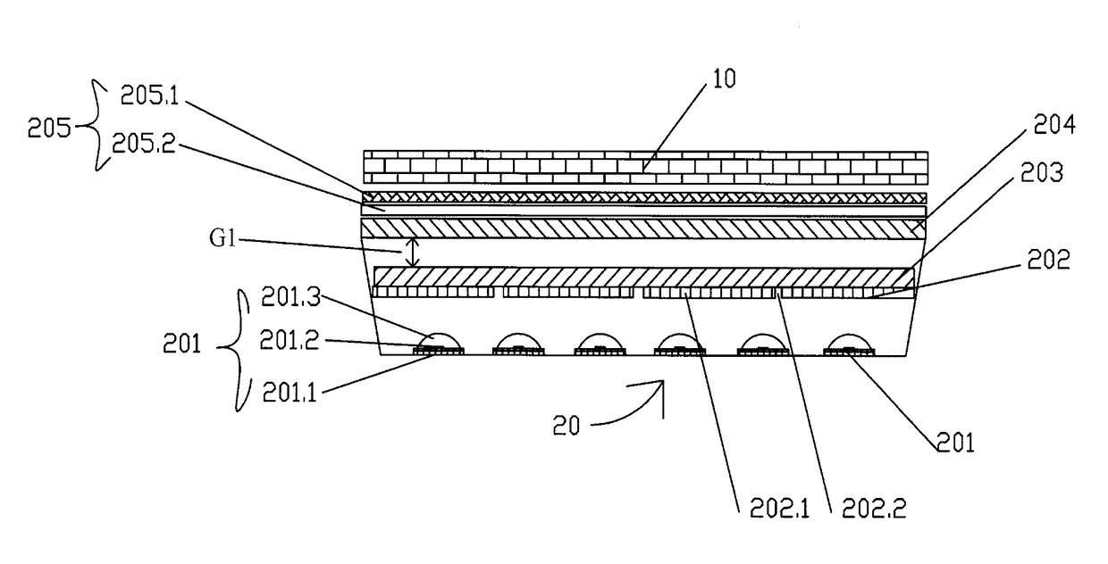
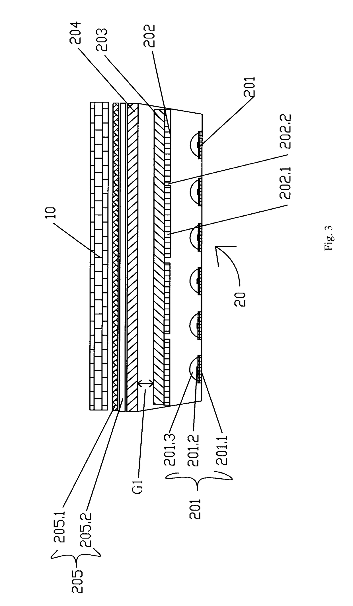
[0042]As shown in FIG. 3, the backlight module 20 further comprises two diffusing plates used for light homogenization. as shown in FIG. 3, two diffusing plates, i.e., a first diffusing plate 203 and a second diffusing plate 204, are provided. A first space G1 is formed between the first diffusing plate 203 and the second diffusing plate 204. The size of G1 is determined by the width of the seams 202.2 formed between two adjacent sub-diaphragms 202.1. The first diffusing plate 203, the second diffusing plate 204, and the first space G1 formed between the first diffusing plate 203 and the second diffusing plate 204 are used for atomizing and homogenizing the light, so that the non-homogeneity of the strength and the color of the light caused by the seams 202.2 between two adjacent sub-diaphragms 202.1 of the quantum dot diaphragm 202 can be neutralized, and thus a better light-emitting effect of the whole backlight module 20 can be ensured. Preferably, the size of the first space G1...

second embodiment

[0052]As shown in FIG. 4, the backlight module 30 further comprises a diffusing plate 303 used for light homogenization. as shown in FIG. 4, a second space G2 is formed between the quantum dot diaphragm 302 and the diffusing plate 303. The size of G2 is determined by the width of the seams 302.2 formed between two adjacent sub-diaphragms 302.1. The diffusing plate 303 and the second space G2 are used for homogenizing the light, so that the non-homogeneity of the strength and the color of the light caused by the seams 302.2 between two adjacent sub-diaphragms 302.1 of the quantum dot diaphragm 302 can be neutralized, and thus a better light-emitting effect of the whole backlight module 30 can be ensured. Preferably, the size of the second space G2 ranges from 3 mm to 15 mm in size, which is the optimized range selected according to the width of the seams 302.2 resulted from current techniques.

[0053]Viewed along the optical path direction, a prism group 305 is arranged on the diffusi...


PUM

PropertyMeasurementUnit
sizeaaaaaaaaaa
wavelengthaaaaaaaaaa
diametersaaaaaaaaaa

Abstract

The present disclosure relates to LCD manufacturing field, and particularly relates to a backlight module. A backlight module is disclosed, said backlight module comprising a light-emitting element, which can emit a first light with a wavelength in a first wavelength range, a quantum dot diaphragm, which is formed by combining a plurality of sub-diaphragms each with a small area together and can emit a second light with a wavelength in a second wavelength range and a third light with a wavelength in a third wavelength range, and a diffusing plate used for light homogenization. The defects of low qualified rate of quantum dot diaphragm with large area manufactured currently and a poor homogeneity thereof can be avoided.

Description

CROSS REFERENCE TO RELATED APPLICATION[0001]The present application claims benefit of Chinese patent application CN 201410440708.9, entitled “Backlight Module” and filed on Sep. 1, 2014, which is incorporated herein by reference.FIELD OF THE INVENTION[0002]The present disclosure relates to the technical field of liquid crystal display, and particularly to a backlight module.BACKGROUND OF THE INVENTION[0003]With the rapid development of the Organic Light-Emitting Diode (OLED) technology, the Liquid Crystal Display (LCD) is facing multiple challenges. Compared with OLED, LCD has certain disadvantages in many aspects, such as thinning, curving, as well as color saturation. More and more attentions are paid to the technological research on these aspects, so that LCD can be comparable to OLED in the aforementioned performances.[0004]With respect to the color saturation, for example, a high color saturation of LCD can be realized through adjusting the Color Filter (CF) of the liquid cryst...

Claims


Application Information

Patent Timeline
Patent Type & Authority Applications(United States)
IPC IPC(8): G02F1/1335F21V8/00
CPCG02F1/133606G02B6/005G02B6/0051G02F2202/36G02F1/133603G02B6/0068G02F2001/133614G02F1/133621G02B6/0053G02F1/133614G02F1/133607
Inventor QIU, YONG YUANSU, ZAN JIA
Owner SHENZHEN CHINA STAR OPTOELECTRONICS TECH CO LTD
Why Eureka
Try Eureka