Solar window construction and methods

a solar collector and solar energy technology, applied in the field of solar collector construction, can solve the problems of inappropriate use as a glass replacement in the window, and achieve the effects of preventing undesired electrical conduction, reducing binding or stress on the exit conductor, and preventing the fold of the conductor from being damaged

Active Publication Date: 2017-06-15
JANOWSKI BRIAN PATRICK
View PDF0 Cites 10 Cited by
  • Summary
  • Abstract
  • Description
  • Claims
  • Application Information

AI Technical Summary

Benefits of technology

[0070]In a casement style window, a compact profile of a bridge portion fits well in the reduced space provided as the sash closes against a frame whereas the elongated profile of a bridge portion accommodates for increased distance between the sash and frame as the window opens.
[0071]In other embodiments a bridge portion conductor is in a resilient form such as an extension spring that is pulled into extension by an opening sash and is biased to spring back to a compact position as the sash is closed. Alternatively, a compression spring is used wherein it is pushed into a smaller compression profile upon closure and returns to an extended profile when the sash is opened. Similarly a coiled spring may be used for this same purpose. The springs may be insulated to prevent undesired electrical conduction.
[0072]In some embodiments one or more of a stile and rail and window frame may include features to guide or house or guide and house a bridge portion of a conductor as it moves between a compact profile and an extended or elongated profile. A bridge recess may be positioned within one or more of a stile, a rail, a jamb liner, and a frame to house at least a portion of a bridge portion of a conductor as needed during sash closure or movement. Optionally a bridge guide may be used to prevent the bridge portion from becoming pinched or crushed during closure as the sash of a casement style window snugs into the frame or moves along the frame of a sliding window. In some forms a bridge guide may be in the form of a piece of plastic, a coiled spring, or guiding wire. In some embodiments a bridge portion is entirely hidden between a rail or stile and frame of the window when the sash of the window is closed. Alternatively, the bridge portion may be concealed within a coupling chamber. A coupling chamber is an enclosed space formed between a closed casement sash and one or more of a window frame and a jamb liner.
[0073]In other embodiments, a portion of the of a bridge portion is visible when a window is closed. For example, an exit conductor may exit a scaffold assembly from an outdoor facing surface of one of the rails or stiles, then extend towards the window frame before reentering the window frame at a nearby outdoor facing surface. Similarly, an exit conduc

Problems solved by technology

Traditional solar collectors are opaque thereby making them inappropriate for use as a glass replacement in windows.
Stationary, also known as fixed wind

Method used


Image

  • Solar window construction and methods
  • Solar window construction and methods
  • Solar window construction and methods

Examples


Embodiment Construction

[0135]Embodiments of the invention will now be described with reference to the Figures, wherein like numerals reflect like elements throughout. The terminology used in the description presented herein is not intended to be interpreted in any limited or restrictive way, simply because it is being utilized in conjunction with detailed description of certain specific embodiments of the invention. Furthermore, embodiments of the invention may include several novel features, no single one of which is solely responsible for its desirable attributes or which is essential to practicing the invention described herein.

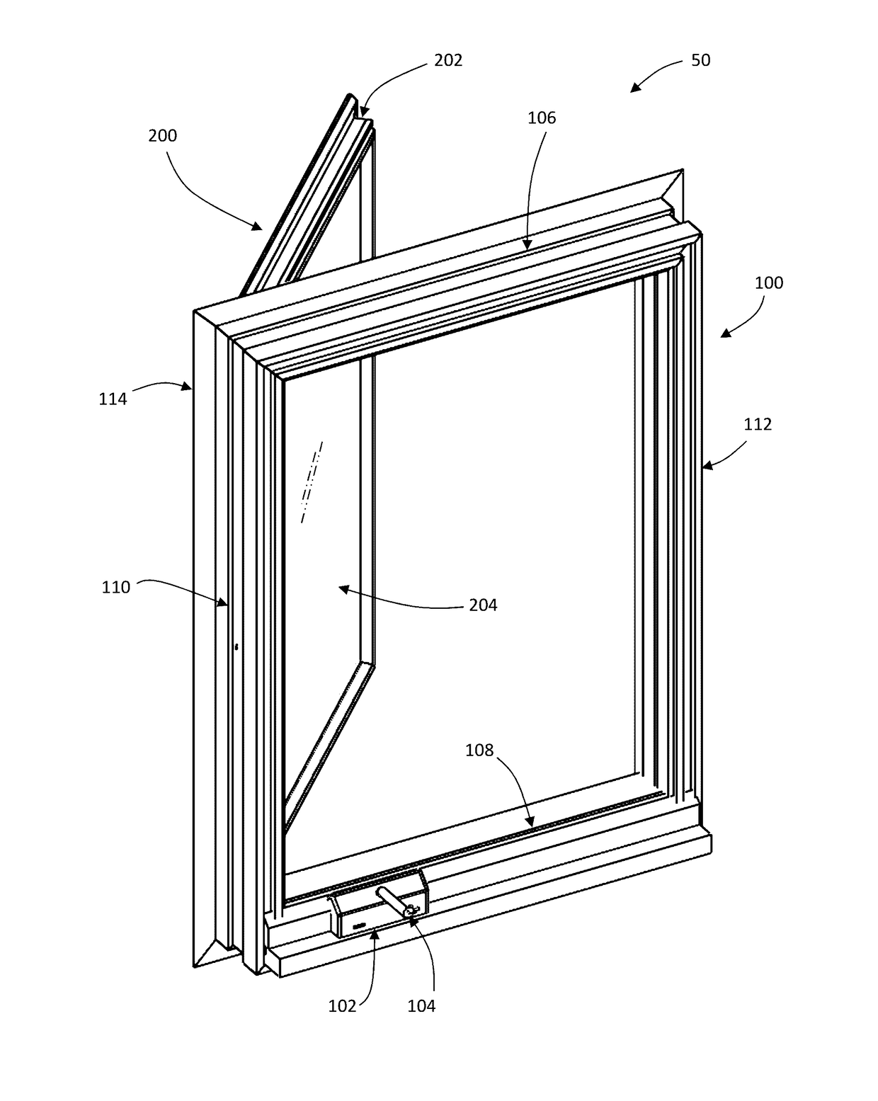
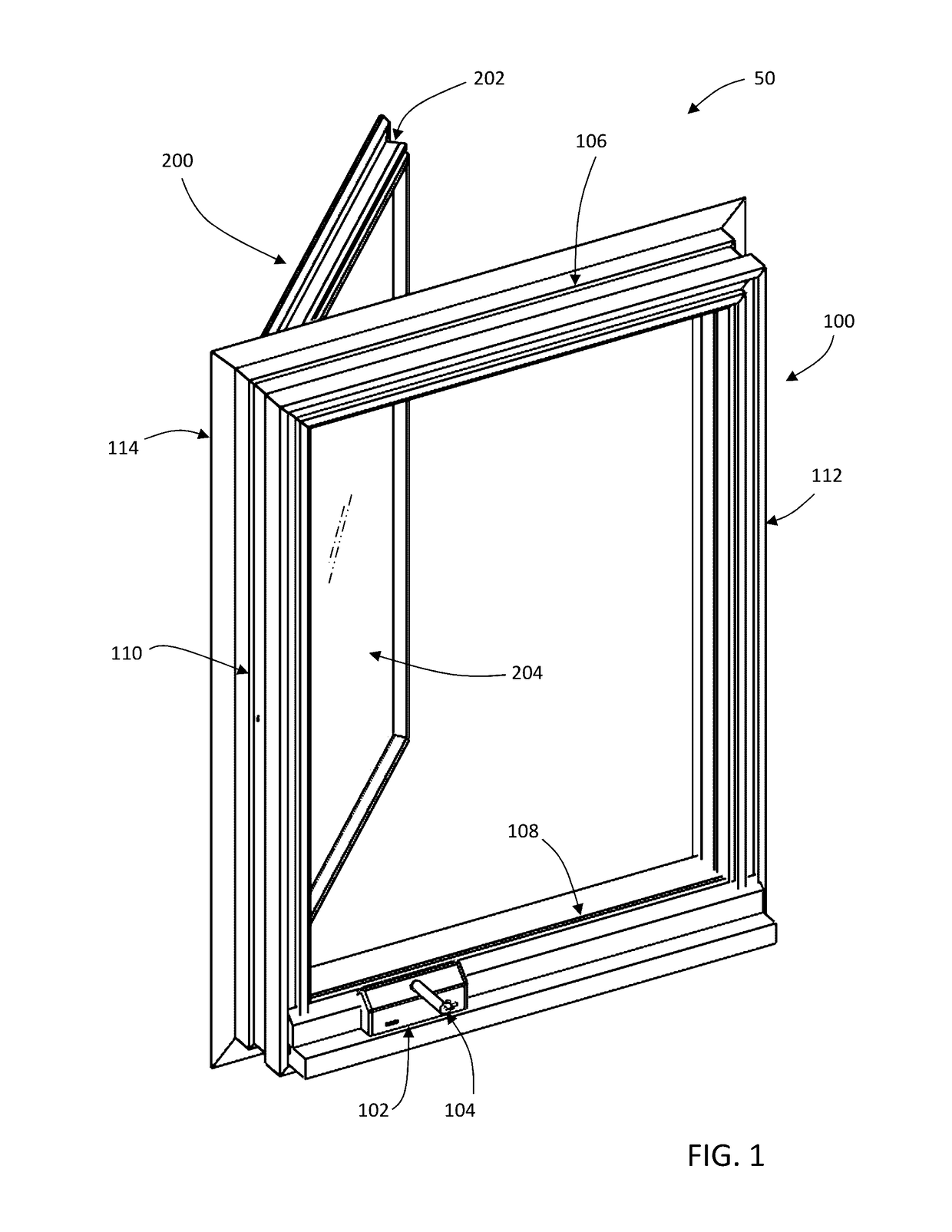
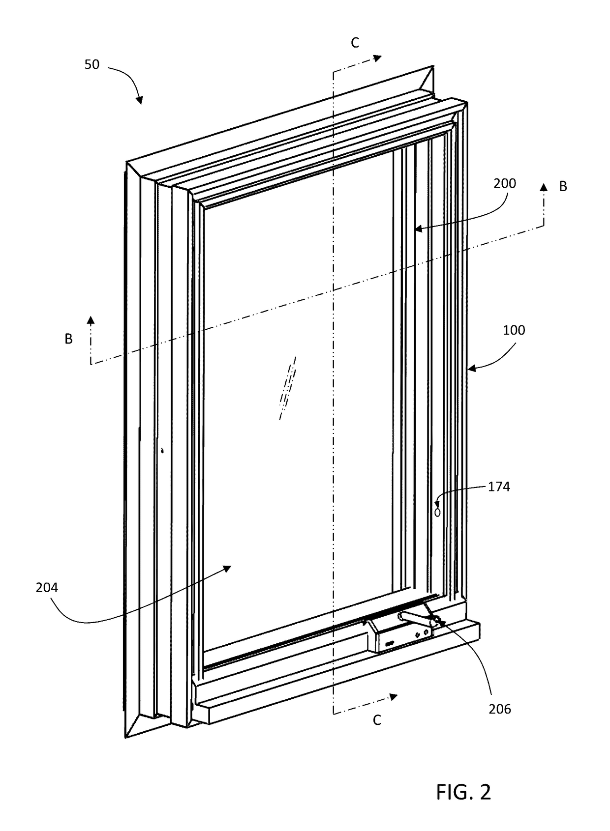
[0136]In a preferred embodiment, the article of invention is in the form of a solar collecting casement window 50 and is illustrated in FIG. 1 (first sash 200 opened) and FIG. 2 (first sash 200 closed). The device comprises a solar collecting first glaze 204 held within a first sash 200. First sash 200 is pivotably connected to a window frame 100 by a hinge and linkage system av...


PUM


Abstract

Disclosed are novel forms of operable windows capable of producing an electrical current utilizing a transparent or semi-transparent solar collecting substrate. A scaffold assembly is utilized to enclose the perimeter of the substrate and one or more solar cells. The scaffold may comprise a scaffold port providing passage for an exit conductor from a sash lead in electrical communication with a solar cell. The assembly may include a bridge portion of an exit conductor that carries electrical current from a sash portion to a frame portion of the window assembly. A frame port extending through the frame of the window may provide passage of the exit conductor to electronic accessories or to circuits that can store or reuse the electrical energy produced. Various forms of electronic accessories are disclosed for fixed or releasable mounting to portions of the window.

Description

[0001]This application is a U.S. non-provisional patent application and claims benefit of priority of U.S. Provisional Patent Application No. 62 / 265,373 filed Dec. 9, 2015.BACKGROUND OF THE INVENTION[0002]Field of the Invention[0003]The invention relates generally to transparent and semi-transparent solar collecting windows, and more particularly to the apparatus and methods of construction of transparent and semi-transparent solar collecting windows and accessories and methods of integrating and use of these accessories with solar collecting windows.[0004]Background Description[0005]As the concern of increasing amounts of greenhouse gases elevates, the world is looking for practical solutions for creating new greener forms of energy. Much has been said in the media about advances in the newer technologies such as electric cars, wind farms, improved batteries, and now solar collectors.[0006]Traditional solar collectors are opaque thereby making them inappropriate for use as a glass ...

Claims


Application Information

Patent Timeline
IPC IPC(8): H02S20/26E06B7/00G02F1/133G02F1/163G02F1/137H02S40/38E06B9/24
CPCH02S20/26H02S40/38E06B7/00E06B9/24G02F1/163G02F2001/13324G02F1/13306E06B2009/2417E06B2009/247E06B2009/2476G02F1/137G02F1/13324Y02B10/10Y02E10/50Y02E70/30
Inventor JANOWSKI, BRIAN PATRICK
Owner JANOWSKI BRIAN PATRICK
Why Eureka
Try Eureka