Magnetometer with a differential type integrated circuit

a technology of integrated circuit and magnetometer, which is applied in the direction of magnetic measurement, instruments, measurement devices, etc., can solve the problem of large noise in the electronics circuit of the sensor, and achieve the effect of improving the signal-noise ratio, high magnetic sensitivity, and excellent high-sensitivity micro-magnetometer

Active Publication Date: 2017-06-22
MAGNE DESIGN
View PDF6 Cites 5 Cited by
  • Summary
  • Abstract
  • Description
  • Claims
  • Application Information

AI Technical Summary

Benefits of technology

[0020]The present magnetometer with a differential-type integrated circuit can detect the coil voltage proportional to the external magnetic field free from the bad influence to the signal voltage caused by the fluctuations of GND electrical potential at the moment of the pulse current passage. Therefore, it can improve its signal-noise ratio, resulting in an excellent high sensitive micro-magnetometer having high magnetic sensitivity, low noise, small size and small power consumption.

Problems solved by technology

But when it passes through the wire, large variations of a grand electrode potential (referred to as “GND” hereinafter) occur to make large noise in the electronics circuit for the sensor.
The reason is that an ASIC receives interference from the GND of the wire and the GND of the coil more strongly than that of the discrete circuit and the GND of the circuit fluctuates to make large noise in the circuit.

Method used


Image

  • Magnetometer with a differential type integrated circuit
  • Magnetometer with a differential type integrated circuit
  • Magnetometer with a differential type integrated circuit

Examples


example 2

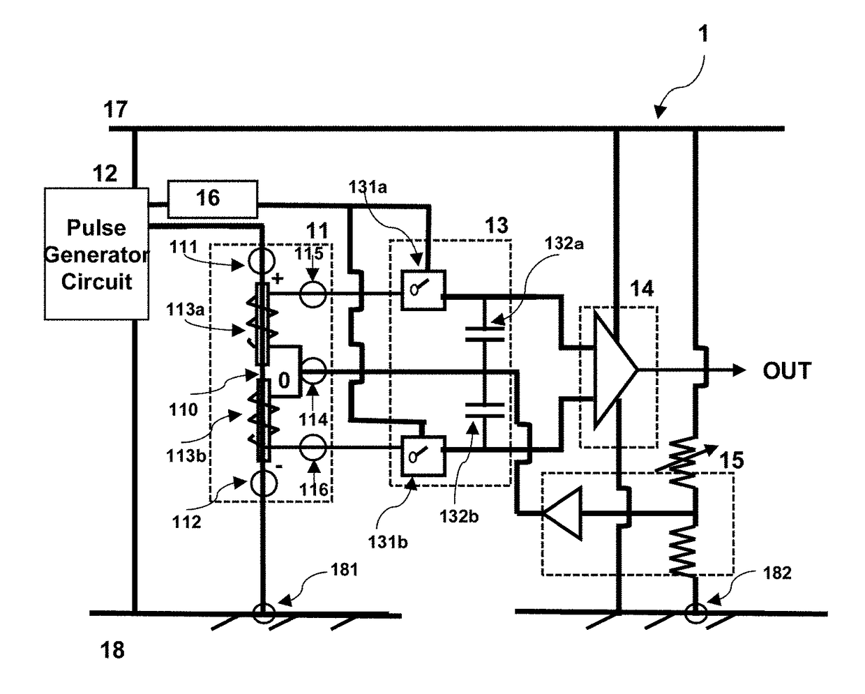
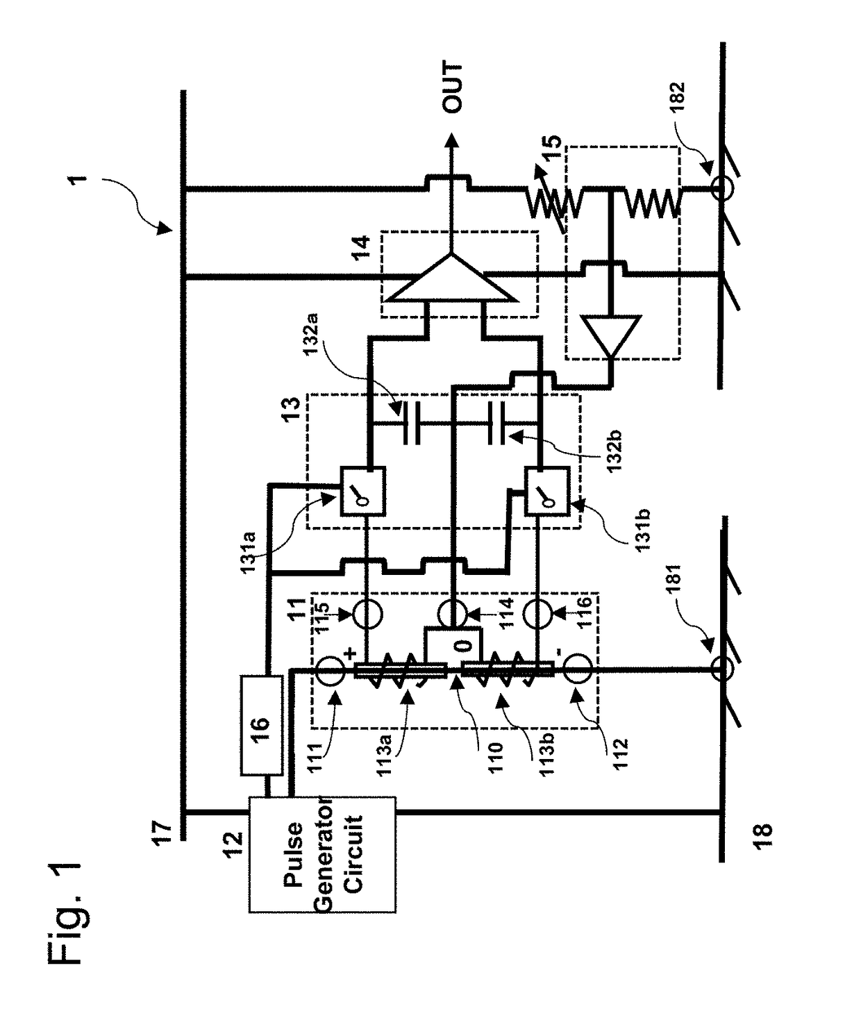
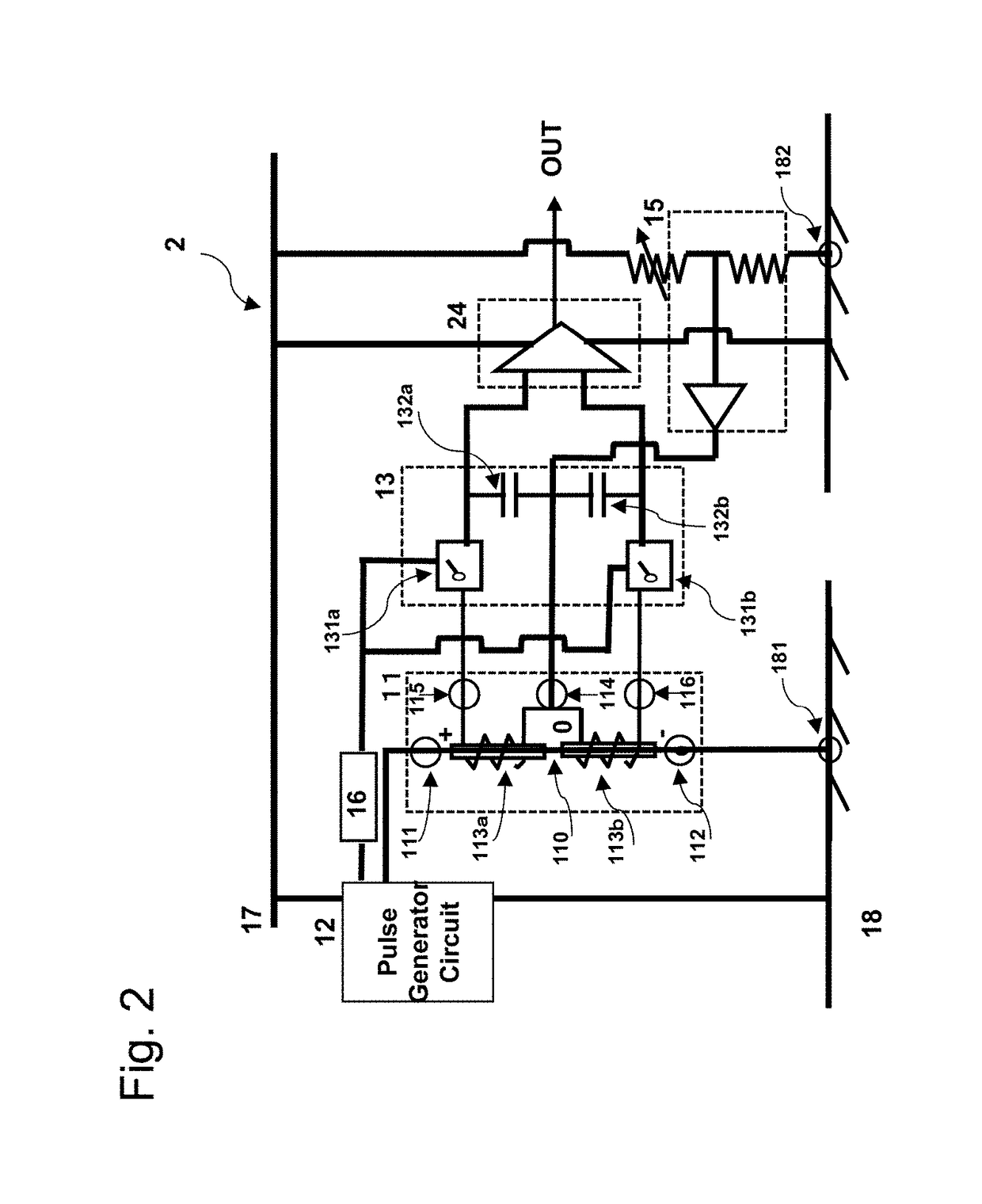
[0035]Example 2 relates to a magnetometer using a GSR sensor applicable to an electronic compass and its circuit block is shown in FIG. 2.

[0036]The magnetometer 2 of Example 2 comprises a differential element 11 with a magnetic wire sensitive to a magnetic field, a pulse generator circuit 12 for supplying a pulse current to the magnetic wire; an adjustment circuit 16 for detection timing, a differential sample holding circuit 13 for holding two coil output voltages with the absolute voltage value of opposite signs against a reference electrode potential set up by the neutral coil electrode 114, a differential ADC 2414 for amplifying the difference voltage between two sample holding coil output voltages, and a potential stabilizing circuit 15 for keeping the voltage of the neutral coil electrode around a middle value of an electronics circuit power source.

[0037]Example 2 is characterized by a differential ADC instead of the differential amplifier circuit of Example 1.

[0038]The differ...

example 3

[0047]Example 3 relates to a magnetometer using GSR sensor for detecting the magnetism of a living body and its circuit block is shown in FIG. 3.

[0048]The magnetometer 3 of Example 3 comprises a differential element 11 that has a magnetic wire sensitive to a magnetic field, a pulse generator circuit 12 for supplying a pulse current to the magnetic wire, an adjustment circuit 16 for detection timing, a buffer circuit before a differential sample holding circuit 13 for holding two coil output voltages with the same absolute voltage value of opposite signs against a reference electrode potential set up by the neutral coil electrode 114, a differential amplifier circuit 14 for amplifying the difference voltage between two sample holding coil output voltages, and a potential stabilizing circuit 15 for keeping the voltage of the neutral coil electrode around a middle value of an electronics circuit power source.

[0049]The differential element has a magnetic wire 110 sensitive to the magnet...


PUM


Abstract

A magnetometer provides a newly designed signal processing circuit that can reduce noise and increase the magnetic sensitivity by means of reducing the noise of GND electrode potential occurred at the timing when the pulse current passes through the magnetic wire. It is characterized by preparing a differential element with a neutral coil electrode, a differential sample holding circuit and a differential amplifier circuit.

Description

CROSS-REFERENCES TO RELATED APPLICATIONS[0001]This application claims the priority of Japanese Patent Application No. 2015-246972 filed on Dec. 18, 2015, entitled “Magnetometer with a Differential Type Integrated Circuit,” which is incorporated herein by reference.BACKGROUND OF THE INVENTION[0002]Technical Field[0003]The present invention relates to a magnetometer with a differential-type integrated circuit that can improve its performance in sensitivity, noise, size and power consumption.[0004]Background Art[0005]High sensitive micro-magnetometers have been used to detect bio-magnetism, the earth magnetism and so on. Nowadays, they are widely used for mobiles phones, smartphones, etc. MI sensors and GSR sensors operated by high frequency pulse current are well known as common types of those micro-magnetometers. They comprise a magnetic sensitive part made by an amorphous wire composed of CoFeSiB and a coil wound around its magnetic wire.[0006]The MI sensor is based on a magneto-imp...

Claims


Application Information

Patent Timeline
Patent Type & Authority Applications(United States)
IPC IPC(8): G01R33/02
CPCG01R33/02G01R33/0023G01R33/028
Inventor HONKURA, YOSHINOBU
Owner MAGNE DESIGN
Why Eureka
Try Eureka