Method of fuel injection control

a fuel injection and control technology, applied in the direction of electric control, combustion engines, machines/engines, etc., can solve the problems of degrading engine performance, higher fuel consumption, and particular full load performance, and achieve the effect of increasing torque, reducing fuel consumption, and reducing fuel consumption

Active Publication Date: 2017-07-06
FORD GLOBAL TECH LLC
View PDF1 Cites 13 Cited by
  • Summary
  • Abstract
  • Description
  • Claims
  • Application Information

AI Technical Summary

Benefits of technology

[0008]By using the split fuel injection when the peak cylinder pressure limits are reached or exceeded, engine efficiency is improved, and maximum torque is achieved while keeping exhaust temperature below the maximum exhaust temperature limit. In this case, splitting the main injection allows more fuel to be injected, thereby producing more torque without increasing exhaust temperatures. By using the split injection to expedite catalyst light-off, the injection timings of the split injection may be shifted to increase exhaust temperatures if they are below the maximum exhaust temperature limit. In this case, the spit injection can also be used to provide a main injection-post injection strategy.
[0009]In this way, a main fuel injection may be split into a first injection that is as advanced as

Problems solved by technology

The inventors herein have recognized that retarding combustion phasing to limit peak cylinder pressures can degrade engine performance, in particular full load performance.
The retarded combustion phasing also results in higher fuel consumption and higher exhaust temperatures than may be possible with more advanced combustion phasing, resulting in the engine's torque and power output being limited.
The issue may be exacerbated when the engine is operating with low energy density fuels such as biodiesel, or other oxygenated fuels.
Likewise, when retarded combustion phasing is used for expediting catalyst heating, there may be an increase in hydrocarbon (HC)

Method used


Image

  • Method of fuel injection control
  • Method of fuel injection control
  • Method of fuel injection control

Examples


Embodiment Construction

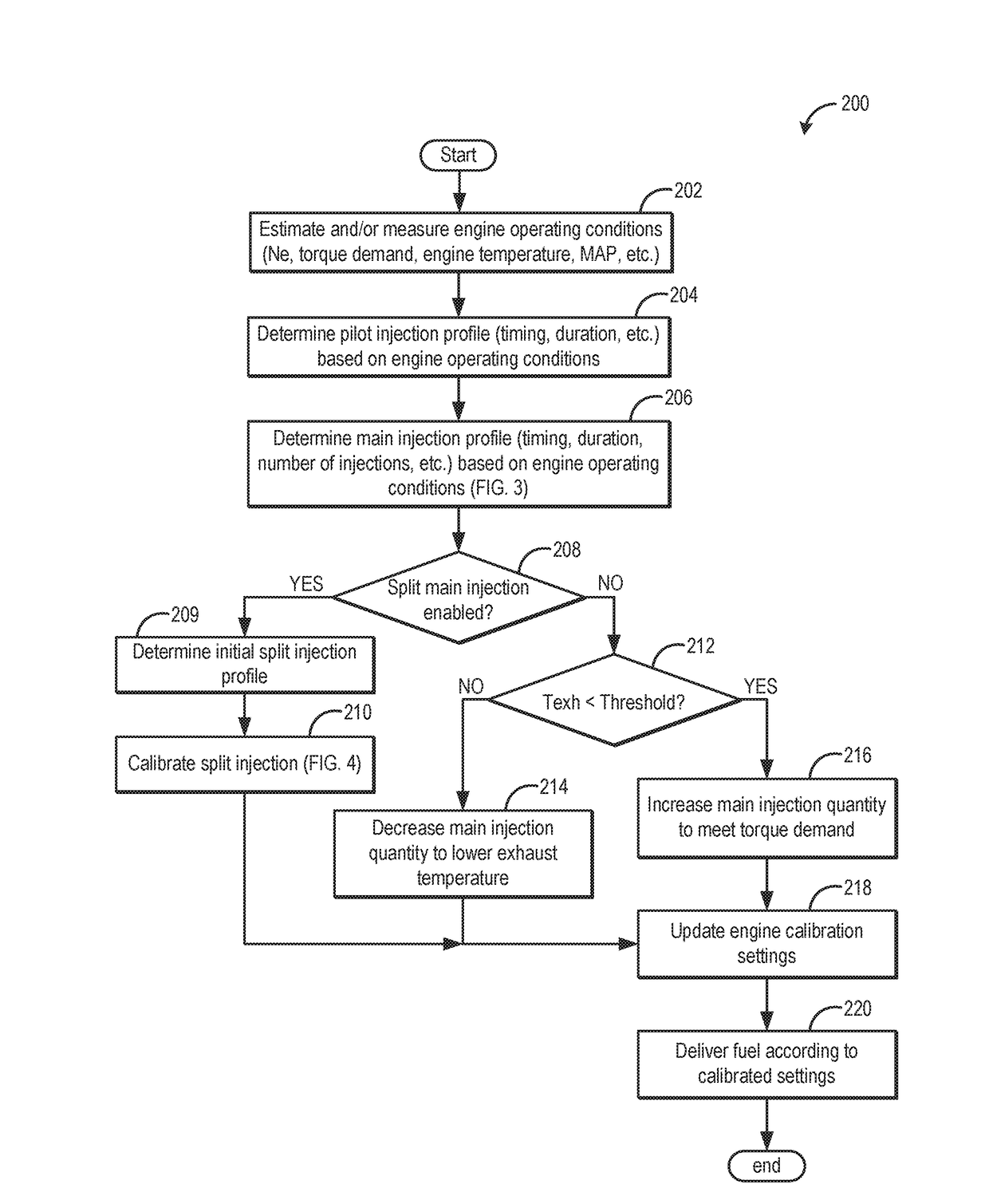
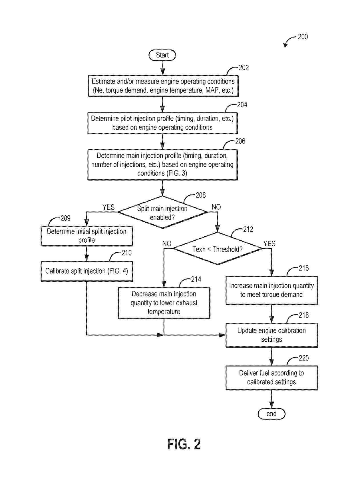
[0017]The following description relates to a method for controlling and adjusting the profile (including timing, amount, and number of injections per cycle) of a main fuel injection and optionally a preceding pilot fuel injection in an engine system, such as the engine system of FIG. 1. An engine controller may perform a control routine, such as the examples routines of FIGS. 2-4 and 6, to split at least a main fuel injection into a cylinder based on engine operating conditions, so as to increase engine torque and power while maintaining cylinder peak pressures within predefined limits. In particular, the engine may be operated with multiple injections per combustion cycle, the injections calibrated based on exhaust temperature and cylinder pressure constraints, as shown in FIG. 5.

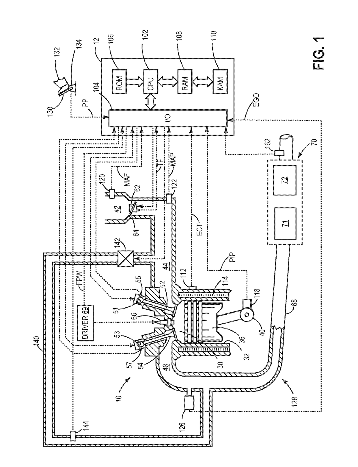
[0018]Referring now to FIG. 1, it shows a schematic diagram with one cylinder of multi-cylinder engine 10, which may be included in a propulsion system of a vehicle. Engine 10 may be controlled at least pa...


PUM


Abstract

Methods and systems are provided for improving engine performance at high load conditions with reduced combustion phasing while maintaining in-cylinder peak pressures within limits. Following a pilot fuel injection, a main fuel injection is split into multiple smaller injections, the smaller injections spread around a timing of the main fuel injection so that peak cylinder pressures for each injection are within cylinder pressure limits. In this way, more enthalpy is created for expediting warming of exhaust catalysts.

Description

TECHNICAL FIELD[0001]The present application relates generally to an internal combustion engine having multiple injections per cylinder per combustion cycle.BACKGROUND AND SUMMARY[0002]During selected engine operating conditions, combustion phasing may be retarded to reduce peak in-cylinder pressures. As such, peak cylinder pressures may be reduced to maintain in-cylinder pressures within a limit above which cylinder integrity can be affected. The retarded combustion phasing may include retarded ignition timing (to a sub-optimal timing) in spark ignition engines, or retarded fuel injection timing in compression ignition engines. Retarded combustion phasing may also be used during engine calibration when an exhaust emission control device (e.g., an after-treatment system coupled to a diesel engine) is not fully functional. The retarded combustion phasing is using therein to increase the exhaust temperature and reduce NOx.[0003]The inventors herein have recognized that retarding combu...

Claims


Application Information

Patent Timeline
IPC IPC(8): F02D41/40F02D41/30F02D41/06
CPCF02D41/403F02D41/064F02D41/401F02D41/3076F02D41/068F02D35/024F02D35/028F02D41/0072F02D41/024F02D41/402F02D2200/0802F02D41/0245F02D41/1446Y02T10/12Y02T10/40
Inventor POLONOWSKI, CHRISTOPHERKURTZ, ERIC MATTHEWLAURI, ANDREWVAN NIEUWSTADT, MICHIEL J.TENNISON, PAUL JOSEPHFINCHUM, JONATHAN
Owner FORD GLOBAL TECH LLC
Why Eureka
Try Eureka