
Wound conductor arrangement and method for insulating a wound conductor

a wound conductor and conductor technology, applied in the direction of insulating conductors/cables, cables, insulated conductors, etc., can solve the problems of health and safety, little development on impregnation process and materials, and time-consuming procedures, so as to reduce production costs and influence the cost of the end product , the effect of simplifying the process

Inactive Publication Date: 2017-07-06
ABB (SCHWEIZ) AG
View PDF18 Cites 1 Cited by
  • Summary
  • Abstract
  • Description
  • Claims
  • Application Information

AI Technical Summary

Benefits of technology

The wound conductor arrangement described in this patent offers a better alternative to traditional insulation methods for electrical devices. It has advantages such as better electrical performance, reduced processing time, and simplified processing steps. The method can be applied to a variety of electrical device shapes and allows for decreased production costs and increased productivity of production lines.

Problems solved by technology

However, these procedures are still time-consuming and require multiple steps.
More remarkably, only little development has been done on the impregnation process and materials with all drawbacks remaining: Handling of liquid resins in the workshops—usually epoxy-anhydride and polyester resin systems—causes health and safety as well as environmental issues due to evaporation of chemical gases from the large VPI tanks.
Both impregnation and curing are time (numerous hours) and energy (heating of large ovens) consuming while also creating chemical fumes that have to be eliminated.
Furthermore, since only low viscosity liquid resins are applicable in this known process, the processes are restricted to thermoset materials only.
The principle of mica tape impregnation—so: filling gaps with liquids—will always bear the risk of voids and partial discharge resulting into a limitation of the design field.

Method used


Image

  • Wound conductor arrangement and method for insulating a wound conductor
  • Wound conductor arrangement and method for insulating a wound conductor
  • Wound conductor arrangement and method for insulating a wound conductor

Examples


Embodiment Construction

[0021]According to embodiments described herein, a wound conductor arrangement is provided, which in particular is used in electric machines. For instance, the wound conductor arrangement according to embodiments described herein may be used in electrical motors, generators, and / or transformers.

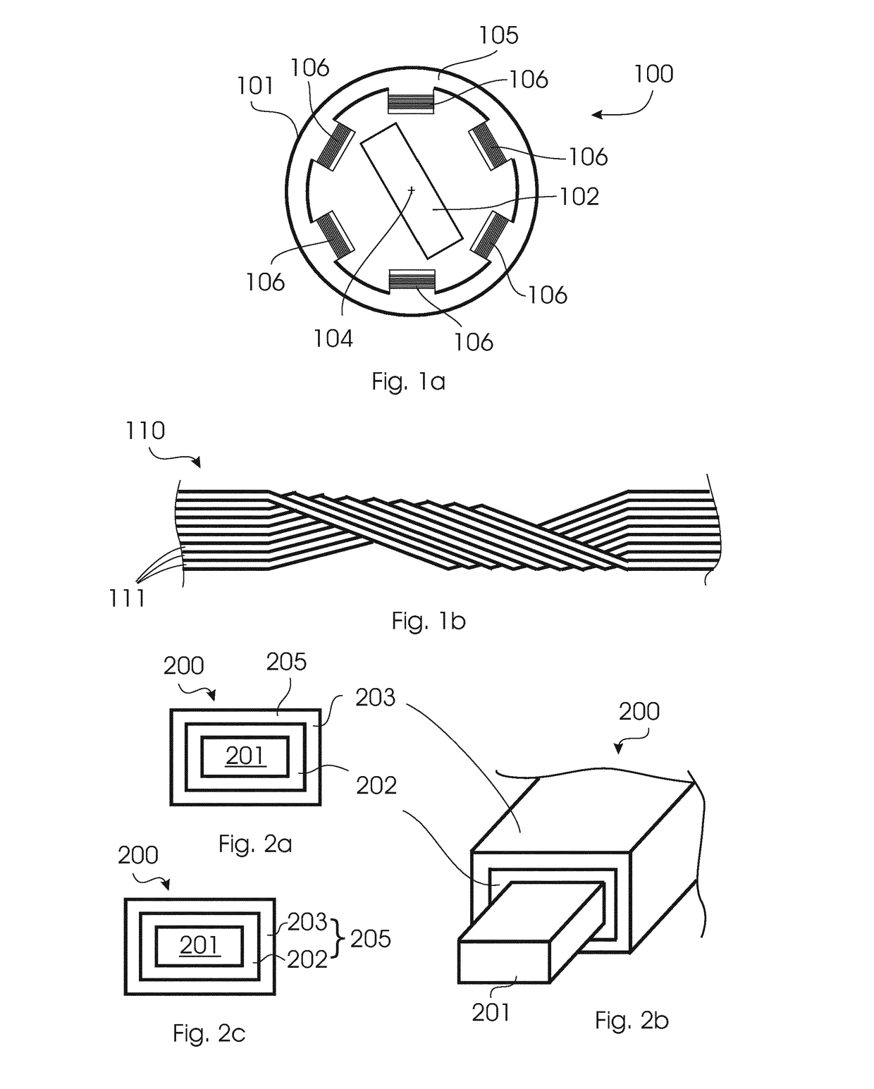
[0022]FIG. 1a shows an example of a wound coil in a basic structure of an electrical motor. The electrical motor 100 includes a stator 101 and a rotor 102.The stator 101 is exemplarily shown having a stator core 105, which is for instance provided in a cylinder-like shape and which is provided with six wound conductors 106 or multi-turns, such as coils or windings, which are connected to a power source. The magnetic rotor 102 (which may also include a wound conductor, which is not shown in FIG. 1a for the sake of simplicity) may be adapted for rotating about an axis 104 pointing in the plane of the drawing sheet. By providing current in the windings 106, a magnetic field is induced. The magne...


PUM

PropertyMeasurementUnit
Temperatureaaaaaaaaaa
Electrical conductivityaaaaaaaaaa

Abstract

It is proposed a wound conductor arrangement for an electrical machine: the wound conductor includes ma wound conductor comprising an electrically conductive material having an electrical conductivity value, and an insulation layer being at least partially provided around the wound conductor by a shrinkable tube comprising insulating material. The wound conductor arrangement further includes an intermediate layer provided between the wound conductor and the insulation layer. The intermediate layer has a conductivity value less than the conductivity value of the wound conductor. Further, an electric machine is proposed including the wound conductor arrangement. A method is described for insulating a wound conductor for an electrical machine.

Description

TECHNICAL FIELD[0001]The invention relates to the field of wound conductors for electrical machines, in particular to the insulation of a wound conductor for an electrical machine. The invention further relates to a method for insulating a wound conductor for an electrical machine.BACKGROUND ART[0002]Wound electrical conductors, such as coils or Roebel bars for an electromotor or generator, are insulated for avoiding contact between the single windings of the coils, but also for avoiding a short between the coil and other conductive components of the electromotor, for example the stator of the electromotor. For instance, the main wall insulation (e.g. mica tape and impregnated resin) is used to insulate a wound conductor on full potential to the stator core on ground potential.[0003]Currently, the so-called vacuum pressure impregnation (VPI) technology is used and widely applied by many machine manufacturers. In this process, layers of mica tape are wound on conductors. The layers o...

Claims


Application Information

Patent Timeline
IPC IPC(8): H02K3/30H01B13/06H01B3/46H01B7/02H01B3/44H01B3/30
CPCH02K3/30H01B3/441H01B3/443H01B13/06H01B3/46H01B7/02H01B3/306H01B3/308H02K3/40
Inventor KRIVDA, ANDREJHO, CHAU-HONGHOUL, CHERIFVAN-LOON, JANXIE, LEITZAVALAS, SPIROS
Owner ABB (SCHWEIZ) AG
Learn More