Sensor system for multi-component fluids

a fluid sensor and multi-component technology, applied in the field of optical sensors and systems, can solve the problems of generating significant service or operating overhead, laborious methods, and significant cost burden,

Inactive Publication Date: 2017-07-20
SAAM INC
View PDF5 Cites 13 Cited by
  • Summary
  • Abstract
  • Description
  • Claims
  • Application Information

AI Technical Summary

Problems solved by technology

These methods are labor intensive and have a significant cost burden because they require the need for reagents, solvent and eventual waste disposal.
While these methods are common, and in many cases required for regulatory or reference measurement reasons, they are considered undesirable and there is a general movement away from them.
This method can be very expensive and may generate a significant service or operating overhead when implemented in a continuous monitoring system, particularly because GC requires the use of high purity compressed gases).
This method is also costly and hard to reduce to a scalable sensor that can be used for commercial sensing applications.
However, these sensors are still limited in spectral range by the wavelength specific LEDs.
Additionally, these embodiments require longer path lengths to efficiently and accurately measure the samples, which requires the sensor package to be large and can require a larger sample.
These larger packages make it harder to implement in certain applications, and may suffer from added environmental interference with the sample.
For example, a fluid sample may freeze under certain conditions due to the larger quantity of fluid needed to measure the sample.
While the infrared spectral region is definitive in terms of the measurement of materials as chemical entities, the measurements can be difficult to implement in terms of the materials used.
More specifically, the optics and associated materials used in these measuring devices are relatively expensive and do not always lend themselves to easy replication for production scale analysis.
Moreover, when multiple devices are implemented into a larger monitoring system used in, for example, industrial process or automotive monitoring applications, these systems often become prohibitively large, complex, and expensive.

Method used


Image

  • Sensor system for multi-component fluids
  • Sensor system for multi-component fluids
  • Sensor system for multi-component fluids

Examples


Embodiment Construction

[0048]It is to be understood that the figures and descriptions of the present invention have been simplified to illustrate elements that are relevant for a clear understanding of the present invention, while eliminating, for purposes of clarity, many other elements found in fluid measuring systems, including those utilizing spectroscopy. However, because such elements are well known in the art, and because they do not facilitate a better understanding of the present invention, a discussion of such elements is not provided herein. The disclosure herein is directed to all such variations and modifications known to those skilled in the art.

[0049]In the following detailed description, reference is made to the accompanying drawings that show, by way of illustration, specific embodiments in which the invention may be practiced. It is to be understood that the various embodiments of the invention, although different, are not necessarily mutually exclusive. Furthermore, a particular feature...


PUM

PropertyMeasurementUnit
wavelengthaaaaaaaaaa
path lengthaaaaaaaaaa

Abstract

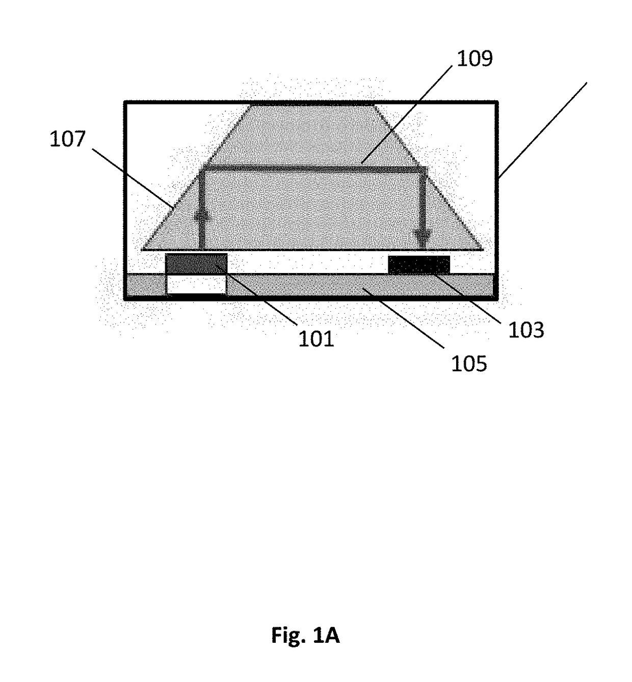
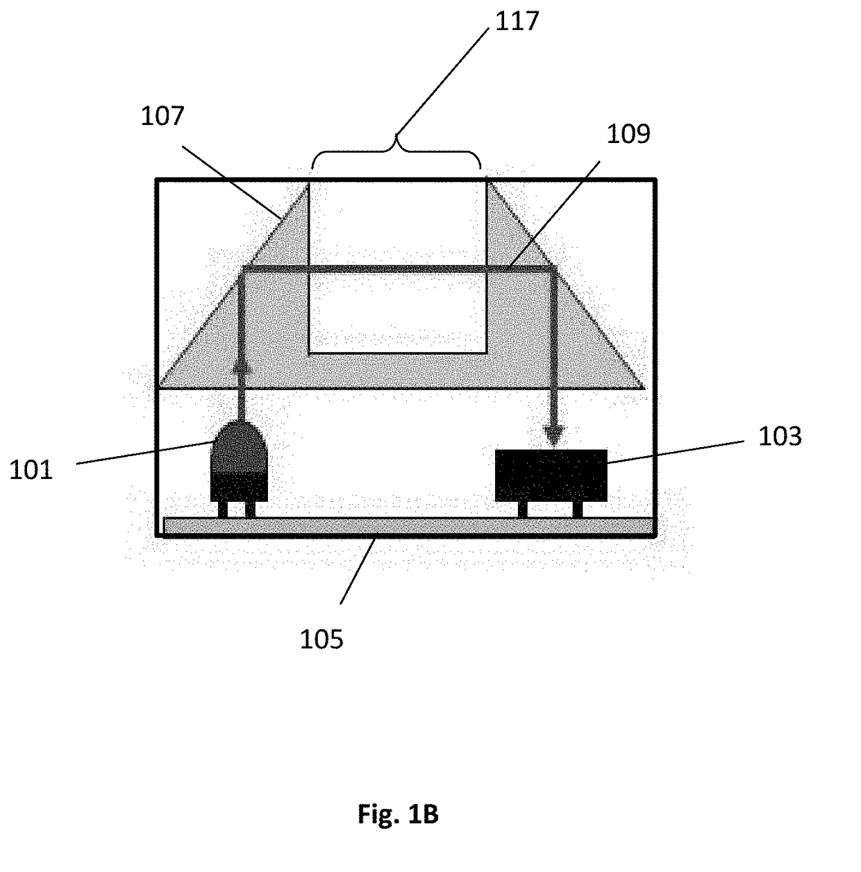
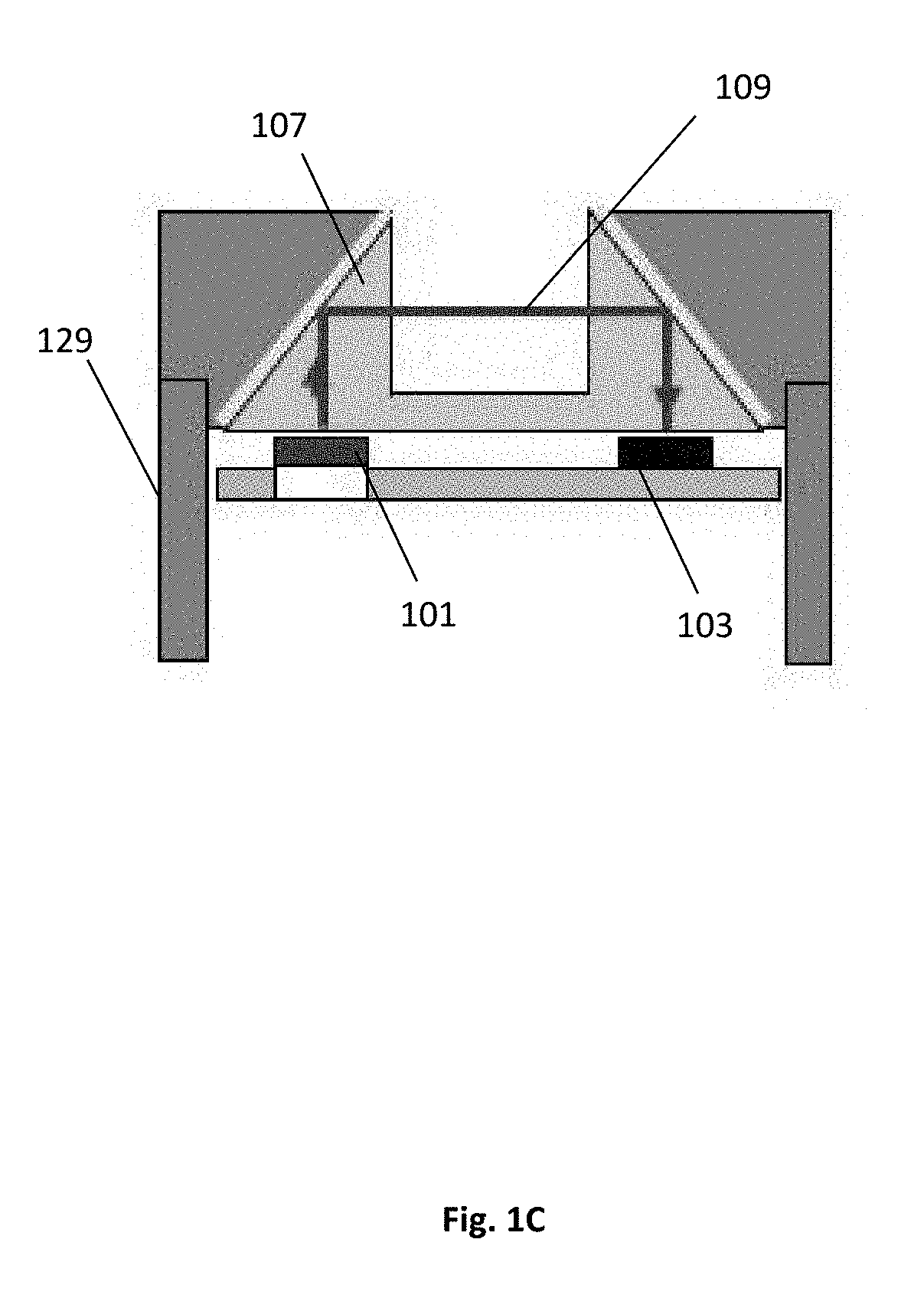
A small scale and low cost spectral sensing system designed primarily for multi-component fluids that provides a compact, low cost platform for analyzers or chemical sensors with limited number of optical and mechanical components featuring a light source, an optical interface with the sample, and a custom detector (multi-element). A single detector element has a specific wavelength, defined by a filter that can be used to select and measure specific chemical compounds. Multiple detector elements are combined to create a multi-channel detector capable of measuring a broad range of wavelengths from ultraviolet (UV) to near and mid-infrared wavelengths. The fabricated sensor can be configured for almost any class of material including gases, vapors, and liquids, with extension to solids. This is linked to the use of the custom detectors featuring filters tailored to specific substances in a broad spectral range from the UV to infrared.

Description

CROSS-REFERENCE TO RELATED APPLICATION[0001]This U.S. Patent Application claims priority to U.S. Provisional 62 / 279,859 filed Jan. 18, 2016, the disclosure of which is considered part of the disclosure of this application and is hereby incorporated by reference in its entirety.FIELD OF THE INVENTION[0002]This invention relates generally to optical sensors, spectroscopy, and associated systems. More particularly, it relates to optical sensors and systems that may be used, for example, for the analysis and characterization of fluids.BACKGROUND[0003]Traditional “wet chemistry” test methods, such as gravimetric or titrimetric methods, such as acid / base and KF moisture titrations are commonly used in laboratories as standard reference methods for determining the component concentrations of a liquid sample. These methods are labor intensive and have a significant cost burden because they require the need for reagents, solvent and eventual waste disposal. While these methods are common, an...

Claims


Application Information

Patent Timeline
Patent Type & Authority Applications(United States)
IPC IPC(8): G01N21/31
CPCG01N21/31G01N2201/08G01N2201/0621G01N21/255G01N21/359G01N21/85G01N21/8507G01J3/0291G01J3/0202G01J3/0205G01J3/0256G01J3/36G01J3/42G01J3/457G01J3/00
Inventor COATES, JOHN
Owner SAAM INC
Why Eureka
Try Eureka